
| “This site contains affiliate links for which OEMDTC may be compensated” |
June 21, 2017 NHTSA CAMPAIGN NUMBER: 17V390000
Possible Transmission Hydraulic Fluid Leak
The loss of hydraulic fluid may prevent the vehicle from shifting out of the gear that it is in. Additionally, if the vehicle is being driven when the fluid level significantly drops, the transmission may shift to an emergency neutral as the vehicle comes to a stop. If the driver ignores the dash warning message and exits the vehicle without applying the parking brake, the vehicle may roll away. Either condition increases the risk of a crash.
NHTSA Campaign Number: 17V390
Manufacturer Aston Martin Lagonda of North America
Components POWER TRAIN
Potential Number of Units Affected 6
Summary
Aston Martin The Americas (Aston Martin) is recalling certain 2012 V8 Vantage vehicles equipped with 6-speed Auto-Shift Manual (ASM) transmissions. A connector for the transmission fluid lines may break resulting in a hydraulic fluid leak.
Remedy
Aston Martin will notify owners, and dealers will replace the clutch pipe, connector assembly, and related brackets, free of charge. The recall began July 18, 2017. Owners may contact Aston Martin customer service at 1-949-379-3100. Aston Martin’s number for this recall is RA-07-0023.
Notes
Owners may also contact the National Highway Traffic Safety Administration Vehicle Safety Hotline at 1-888-327-4236 (TTY 1-800-424-9153), or go to www.safercar.gov.
Check if your Aston Martin has a Recall
SAFETY RECALL ACTION
| Reference number: | RA-07-0023 | Issued: 6 July, 2017 | |
| Subject: | Connector failure on V8 Vantage 6-Speed SportShift Transmission | ||
| Model(s): | V8 Vantage with 6-Speed SportShift Transmission | ||
| VIN range: | Refer to the separately published list of VINs | ||
| Applicable to: | All Dealers | ||
| Distribute to: | After Sales Manager
Executive Manager Service Manager Sales Manager |
Warranty Staff
Technician(s) Parts Staff |
|
Attached Documents:
- Appendix A – Table that Shows the Quantities of Affected Vehicles.
- Copy of the Owner Notification letter for vehicles in RA-07-0023.
- Copy of the Change of Keeper or Address form.
Reason for this Recall Action
This Recall Action is applicable to the vehicles that follow:
- V8 Vantage Coupe and Roadster with 6-Speed “SportShift” transmission manufactured from October November 2011.
Aston Martin has determined that a defect which relates to motor vehicle safety exists on a range of V8 Vantage vehicles that were manufactured from September thru November 2011.
From VIN C15849, the 6-speed ASM transmission installed on V8 Vantage, has a different design of connector between the pipe for the clutch fluid and the ASM (Auto-Shift Manual) system. It is possible that this connector can fail and cause loss of the clutch fluid.
Detailed description of the problem
If the hydraulic fluid leaks, the level will go down. As the fluid level goes down, the following can occur:
- The driver may see signs of fluid below the vehicle or underneath on the ground.
- At start-up, an “Unable to select gears” warning will display in the driver’s display and the transmission will not change from Neutral or Park into a gear. The driver will be unable to move the vehicle.
- While driving, an “Unable to select gears” warning will flash and the driver can continue in the same gear until they choose a place to stop. In this condition, if the driver operates the brakes, the engine can be stalled as the vehicle comes to a stop.
- If, in the case above there is sufficient pressure remaining in the hydraulic system, the transmission will select emergency neutral as the vehicle comes to a stop.
Note: It is possible that a vehicle has had the connector replaced before by Service Bulletin SB-07-0401. Refer to Part A of this procedure. If the installed connector is type B shown in Figure 3, you do not need to do this workshop procedure.
To correct the problem
To correct this problem, you must:
- Do a check to see if Service Bulletin SB-07-0401 has been completed on the vehicle.
- If necessary, install a new connector and support bracket.
The full list of VINs for the affected vehicles is on the DCS portal as an attachment to this Recall Action document.
PLEASE DO A CHECK OF ALL VEHICLES THAT ARE IN THE AFFECTED VIN LIST
Legal Requirements
The National Traffic and Motor Vehicle Safety Act, as amended, provides that each vehicle which is subject to a recall campaign of this type must be adequately repaired within a reasonable time after the owner has tendered it for repair. Failure to repair within sixty (60) days after tender of a vehicle is prima facie evidence of failure to repair within a reasonable time.
If the condition is not adequately repaired within a reasonable time, the owner may be entitled to an identical or reasonable equivalent vehicle at no charge, or to a refund of the purchase price less a reasonable allowance for depreciation.
To avoid having to provide these difficult solutions, every effort must be made to promptly schedule an appointment with each owner and to repair their vehicle as soon as possible. As you will see in reading the attached copies of the letters that are being sent to Owners, the Owners are being instructed to contact Aston Martin Customer Service if their Dealer does not correct the condition within three (3) days of the mutually agreed upon service date. If the condition is not corrected within a reasonable time, they are instructed on how to contact the National Highway Traffic Safety Administration.
IMPORTANT: We remind you that it can be a violation of Section 30120(i) of the Federal Motor Vehicle Safety Act required under this notice if a Dealer sells or leases a vehicle that is covered by this notice without first completing the repair.
Communications
We will write to every owner directly to tell them about this Safety Recall Action. A copy of the letter is attached at the end of this Recall Action for your information. There is also a copy of the “Change of Keeper’s Address or Ownership” form.
When the Owner calls to make an appointment, briefly describe the remedial work which will be done to the Owner’s vehicle and fully explain the reason for this work. Tell the owner that the repair will be done at no cost to them.
Service Reception Desk – Checks you must do before you book the vehicle in.
When you make a reservation for a Customer that you confirm the name and contact details are correct in Aston Martin’s records.
To do this, please do the steps that follow:
- Enter the vehicle’s 6-digit chassis number into DCS (amdealers.com) and click “Validate” (refer to Figure 1).
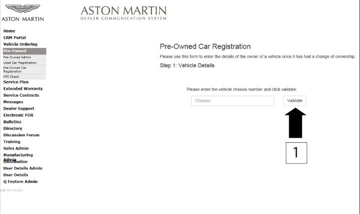 Figure 1
- Make sure that the vehicle details are correct. If the current owner is correct, no action is necessary.
- Make sure that the Customer name is correct. If the data is correct, then no action is necessary.
- To update the Customer details, use the search feature to find the customer in your Synergy database (refer to Figure 2).
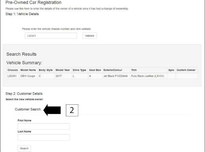 Figure 2
Note: The Customer record and updated details must have been entered into Synergy before you try to transfer the ownership in DCS.
- If the correct Customer shows, click “confirm”.
- If the correct Customer details do not show, click “add new”.
Before you start work
Log on to the Online Dealer Warranty (ODW) system. Do the steps that follow:
- Select the Warranty Live screen (Outstanding Campaigns Status).
- Download the attached VIN list from the DCS Portal and do a check of the VINs in your control.
- Find out if there are other open Service Actions (SAs) or Recall Actions (RAs) for the vehicles in the list.
- List the SAs and RAs and plan the work so that the Owner only needs to come to your Dealership once.
Note: The ODW system operates in real-time. Thus, the online condition shows only the newest Dealer Warranty Claim submissions.
Workshop Procedure
This Workshop Procedure has the parts that follow:
- Part A – Inspect the connector for the clutch fluid line.
- Part B – Remove the transaxle assembly.
- Part C – Remove the torque tube assembly.
- Part D – Change the supply tube assembly for the concentric slave cylinder.
- Part E – Change the hose for the dry break connector.
- Part F – Install the torque tube assembly.
- Part G – Install the transaxle assembly.
Part A – Inspect the connector for the clutch fluid line
- Raise the vehicle and make it safe.
- Use an endoscope to examine the connector between the clutch fluid tube and the transmission.
- If the connector is the same as type “A” shown in Figure 3, continue from Part B.
- If the connector is the same as type “B” shown in Figure 3, you do not need to do more work.
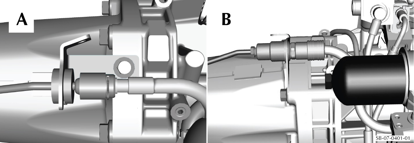 Figure 3
Part B – Remove the transaxle assembly
WARNING: THE EXHAUST SYTEM WILL BE VERY HOT AFTER OPERATION AND CAN BURN YOU. LET THE EXHAUST SYSTEM BECOME COOL BEFORE YOU DO WORK ON THE SYSTEM.
- Make sure that the transmission is in neutral gear.
- Use an applicable strap to attach the vehicle to the lift.
- Do the battery disconnect procedure (refer to Workshop Manual procedure 14.01.CA).
- Lift the vehicle and make it safe.
- Drain the oil from the transaxle (refer to Workshop Manual procedure 07.03.BC).
- Hold the cross brace (2). Remove the four screws (1) that attach the cross brace (2) and remove the cross brace (2) (refer to Figure 4).
 Figure 4
- Remove the four bolts and collect the four springs that attach the exhaust centre pipe to the muffler and bypass valve assembly (refer to Figure 5).
 Figure 5
- Loosen the two bolts on the clamps that attach the catalytic converter and pipe assemblies to the centre exhaust pipe (refer to Figure 6).
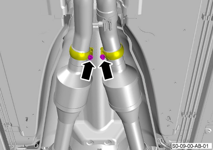 Figure 6
- Move the two clamps on the catalytic converter and pipe assemblies away from the centre exhaust pipe (refer to Figure 7).
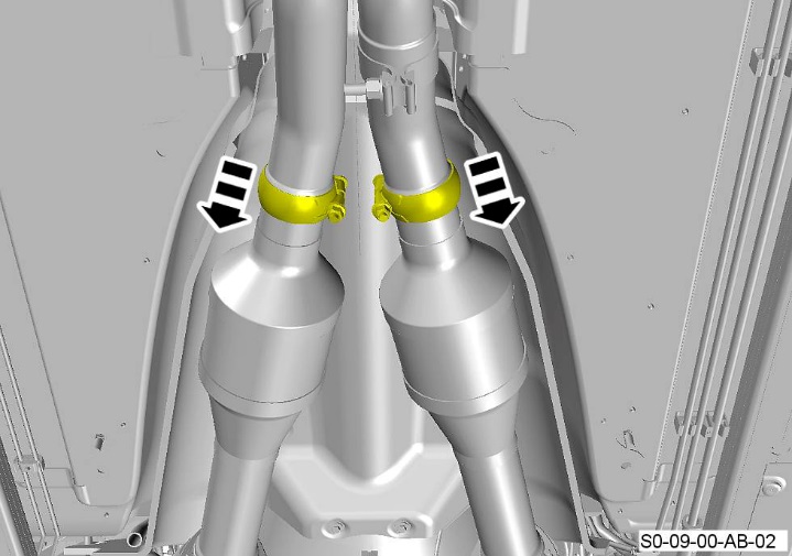 Figure 7
- Put an applicable support below the centre exhaust pipe.
WARNING: THE EXHAUST PIPES ARE HEAVY. GET THE AID OF ONE MORE PERSON WHEN YOU DO THE STEPS THAT FOLLOW.
- Remove the four attachment bolts for the centre exhaust mounting (refer to Figure 8).
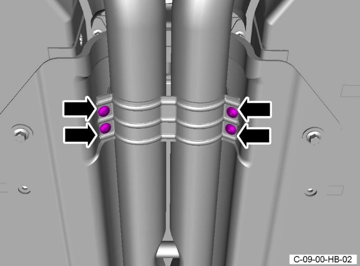 Figure 8
- Loosen the two clamp nuts and release the centre pipe from the two catalysts.
- Remove the centre pipe and the rear exhaust pipes as an assembly (refer to Figure 9).
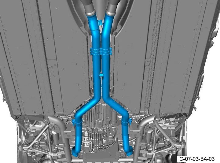 Figure 9
- Remove and discard the two sealing rings (refer to Figure 10).
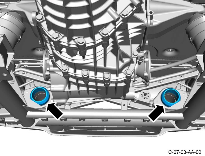 Figure 10
- Remove the exhaust centre brace assembly (refer to Figure 11).
 Figure 11
- Remove the four bolts and four washers (1) that attach the tunnel heatshield (2) to the body. Remove the heatshield (2) (refer to Figure 12).
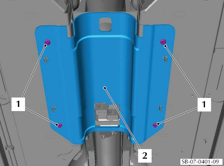 Figure 12
- Remove the eight bolts (1) that attach the tunnel reinforcement plate (2) to the body and remove the plate (2) (refer to Figure 13).
 Figure 13
- Remove the bolt (1) that attaches the ground cable (2) to the transmission mount bracket (3) and move the ground cable (2) away (refer to Figure 14).
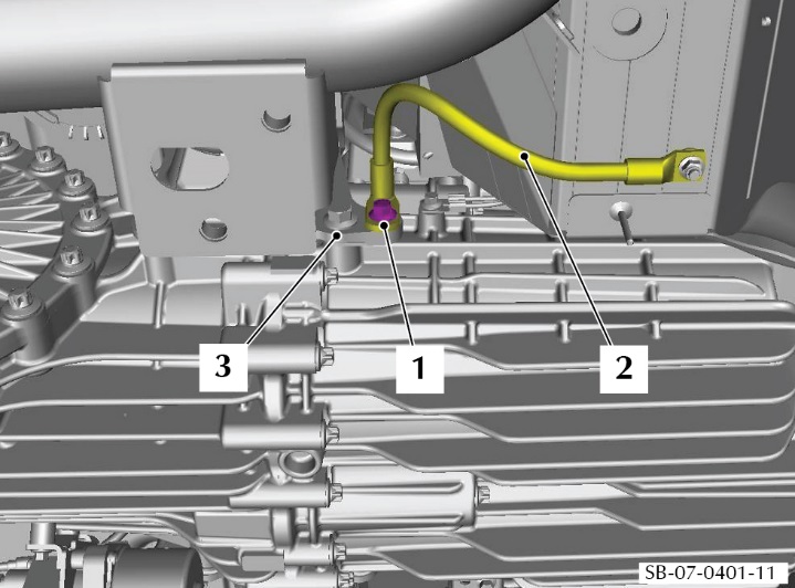 Figure 14
- Make a mark on each of the two drive shafts to differential flanges for alignment during assembly.
- Remove and discard the six Allen head bolts that attach the left drive shaft flange to the transaxle. Collect the three locking plates from the drive shaft flange (refer to Figure 15).
 Figure 15
- Remove and discard the six Allen-head bolts that attach the right drive shaft flange to the transaxle. Collect the three locking plates from the drive shaft flange (refer to Figure 16).
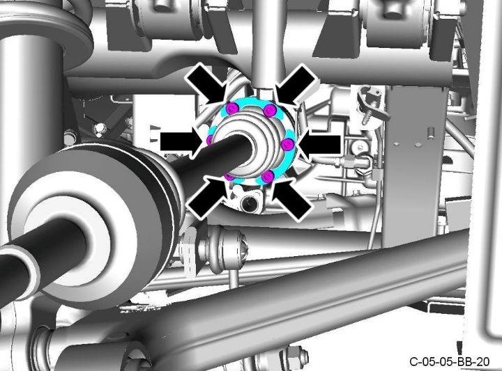 Figure 16
- Disconnect the breather pipe from the transaxle and move the pipe away (refer to Figure 17).
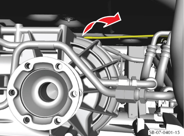 Figure 17
- Put a transmission lift below the transaxle.
- Adjust the height of the transmission lift to hold the weight of the transaxle.
- Remove the nut that attaches the right-side transaxle mount to the rear subframe (refer to Figure 18).
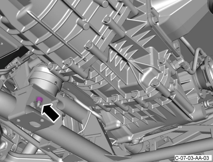 Figure 18
- Remove the nut that attaches the left-side transaxle mount to the rear subframe (refer to Figure 19).
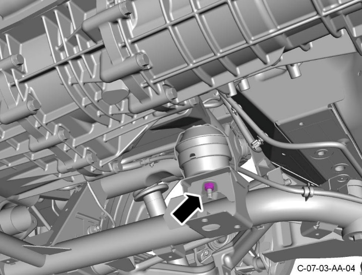 Figure 19
- Remove and discard the four bolts that attach the right-side transaxle mount bracket to the transaxle. Remove the mount bracket with the hydramount attached (refer to Figure 20).
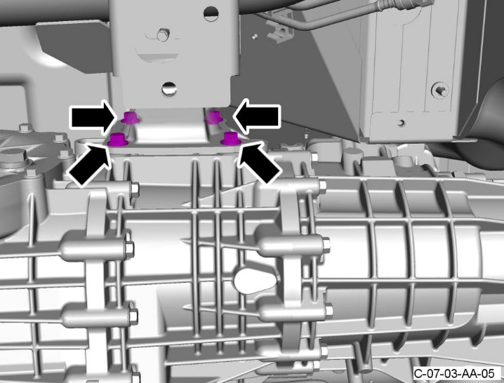 Figure 20
- Release the reservoir hose (1) from the two clips (2) that attach it to the left-side mount bracket (refer to Figure 21).
 Figure 21
- Remove the screw (1) to release the clamp (2) that attaches the fluid reservoir (3) (refer to Figure 22).
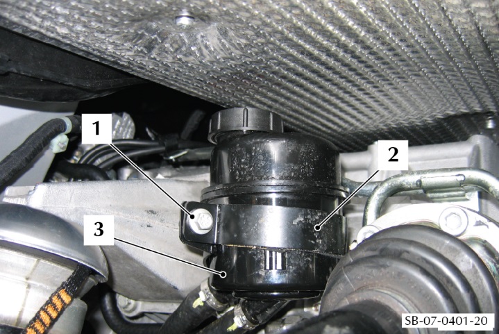 Figure 22
- Remove the clamp (2) and move the reservoir (3) away.
- Remove the two screws that attach the reservoir mounting bracket to the transaxle mount bracket and remove the reservoir mounting bracket.
- Remove and discard the four bolts that attach the left side mount bracket to the transaxle. Remove the mount bracket with the hydramount attached (refer to Figure 23).
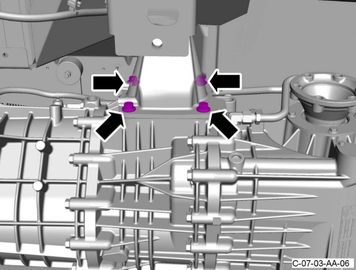 Figure 23
- Release the drive shafts from the transaxle and move them away.
- Use the transmission lift to lower the transaxle sufficiently to get access to the clip (1) that attaches the electrical harness (2) to the subframe (3). Release the clip (1) from the subframe (2) (refer to Figure 24).
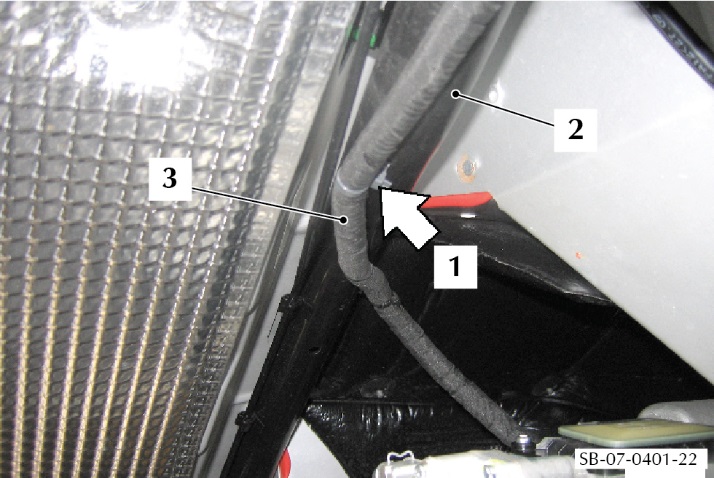 Figure 24
- Lower the transaxle to approximately 420 mm from the installed position and use applicable straps to hold it onto the hydraulic lift.
- Remove the clip (1) (if it is still installed) that holds the clutch hose connector (2) together at the joint between the transaxle and the torque tube (refer to Figure 25).
- Disconnect the hose (2).
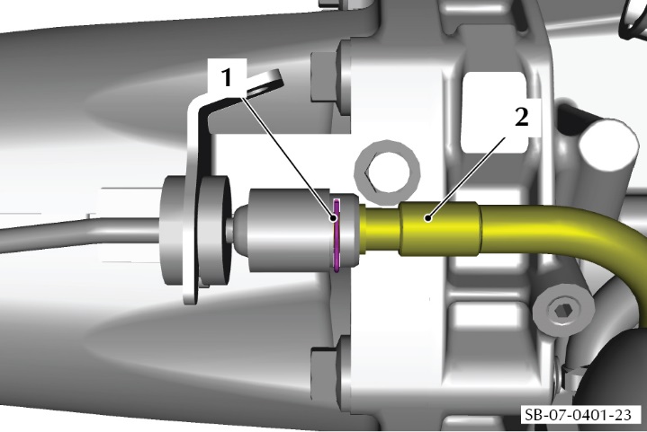 Figure 25
- Remove the screw that attaches each of the two ground connections (1 and 2) to the transaxle (refer to Figure 26).
- Release the clip (3) that attaches the electrical harness.
- Disconnect the electrical connector (4) from the ASM pump.
- Disconnect the five electrical connectors (5) from the valve block.
- Disconnect the electrical connector (6) from the control module.
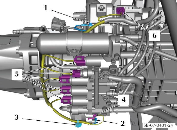 Figure 26
- Move the electrical harness away from the transaxle.
- Put an applicable support in position to hold the torque tube.
- Use applicable straps to attach the torque tube to the transmission lift.
WARNING: THE TRANSAXLE ASSEMBLY IS VERY HEAVY. GET THE AID OF ONE MORE PERSON WHEN YOU MOVE THE TRANSAXLE. IF YOU DO NOT, PERSONAL INJURY CAN OCCUR.
- Remove the eight bolts that attach the transaxle to the torque tube (refer to Figure 27).
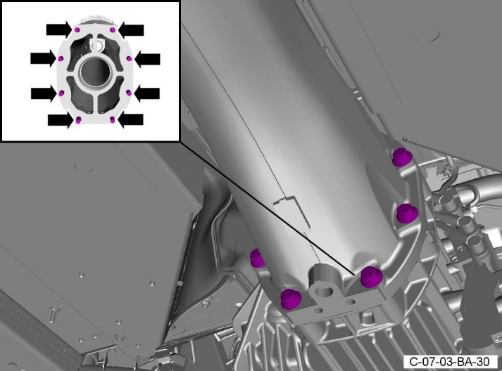 Figure 27
- Move the transaxle rearward to give clearance between the torque tube and the transaxle.
- Remove the transaxle.
Part C – Remove the torque tube assembly
- Remove the circlip that keeps the propeller shaft in the torque tube (refer Figure 28).
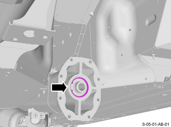 Figure 28
CAUTION: THE PROPELLER SHAFT IS LARGE. GET THE AID OF ONE MORE PERSON WHEN YOU REMOVE THE PROPELLER SHAFT. IF YOU DO NOT, DAMAGE CAN OCCUR.
CAUTION: BE CAREFUL WHEN YOU REMOVE THE PROPELLER SHAFT. YOU CAN EASILY DAMAGE THE SPLINES IN THE CLUTCH WHEN YOU REMOVE THE PROPELLER SHAFT.
- Carefully remove the propeller shaft from the torque tube (refer to Figure 29).
 Figure 29
- Remove the nut that attaches the heat shield for the front floor to the body (refer to Figure 30).
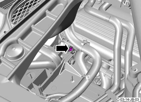 Figure 30
- Remove the nut that attaches the heat shield for the front floor to the body Figure 31.
 Figure 31
- Remove the two screws (1) that attach the front of the heat shield (2) for the front floor to the torque tube (refer to Figure 32).
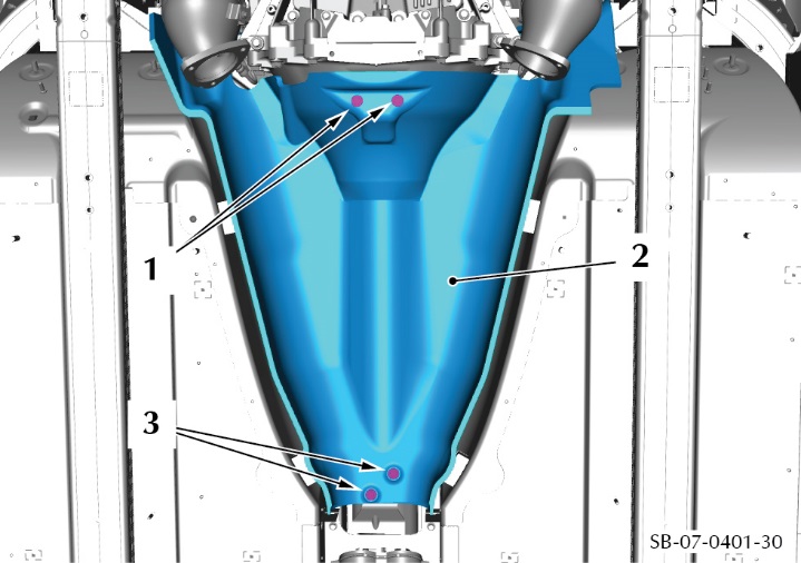 Figure 32
- Remove the two screws (3) that attach the rear of the heat shield (2) to the torque tube and remove the heat shield (2).
- Disconnect the electrical connector from the speed sensor for the propeller shaft (refer to Figure 33).
 Figure 33
- Use the transmission jack to lower the rear end of the torque tube until you can get access to the 16 torque tube attachment bolts.
- Remove the 16 bolts that attach the torque tube to the engine and remove the torque tube (refer to Figure 34).
 Figure 34
WARNING: THE TORQUE TUBE IS LARGE AND HEAVY. GET THE AID OF ONE MORE PERSON WHEN YOU REMOVE THE TORQUE TUBE. IF YOU DO NOT, PERSONAL INJURY CAN OCCUR.
- Remove the torque tube.
Part D – Change the supply tube assembly for the concentric slave cylinder
- Remove the clip (1) that attaches the connector (2) for the clutch fluid tube assembly (tube assembly) to the concentric slave cylinder (3) (cylinder) (refer to Figure 35).
- Disconnect the tube assembly (2) from the cylinder (3) (refer to Figure 35).
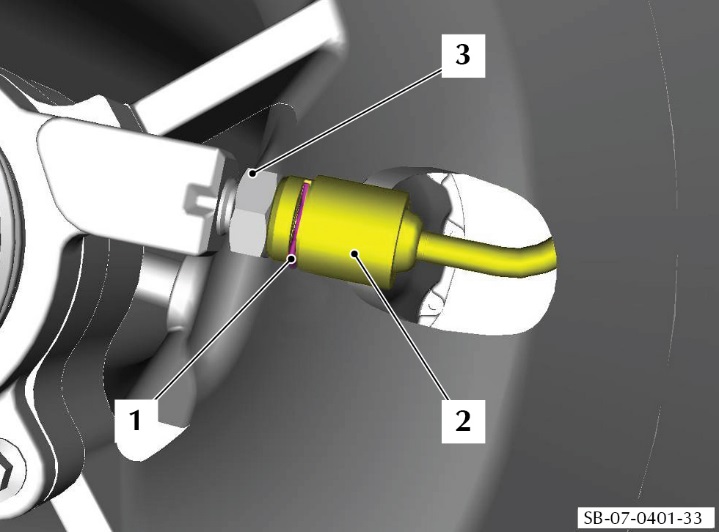 Figure 35
- Remove the screw (1) that attaches the attachment bracket (2) for the tube assembly (3) to the torque tube (refer to Figure 36).
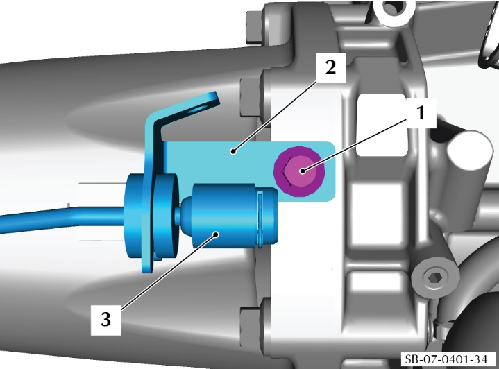 Figure 36
- Release the tube assembly from the clips that attach it to the torque tube.
- Discard the tube assembly.
- Install the new tube assembly (refer to Part Data) into the clips on the torque tube.
- Connect the tube assembly (2) to the concentric slave cylinder (3) (refer to Figure 37).
- Install a new clip (1) to attach the tube assembly (2) to the concentric slave cylinder (3).
 Figure 37
Part E – Change the hose for the dry break connector
- On the transaxle assembly, remove the clip (1) that attaches the clutch fluid hose (2) into the valve block (3) (refer to Figure 38).
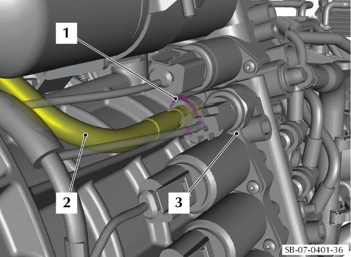 Figure 38
- Disconnect the clutch fluid hose (2) from the valve block (3).
- Discard the clutch fluid hose (2).
- Install the new hose (2) from the EVO pipe kit C (refer to Part Data).
- Install the new retaining clip (1) to hold the hose (2) into the valve block (3).
Part F – Install the torque tube assembly
WARNING: THE TORQUE TUBE IS LARGE AND HEAVY. GET THE AID OF ONE MORE PERSON WHEN YOU INSTALL THE TORQUE TUBE. IF YOU DO NOT, PERSONAL INJURY CAN OCCUR.
- Clean the mating faces between the torque tube and the engine.
- Align the torque tube assembly with the engine.
- Install the 16 bolts that attach the torque tube assembly to the engine (refer to Figure 39).
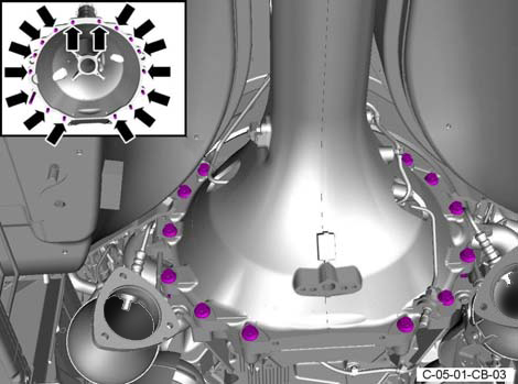 Figure 39
- Torque the 16 bolts to 50 Nm.
- Connect the electrical connector to the speed sensor for the propeller shaft (refer to Figure 40).
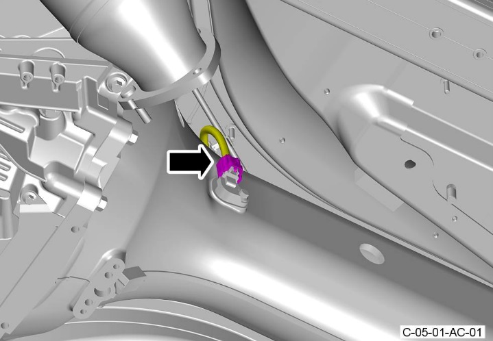 Figure 40
- Put the heat shield (2) into position (refer to Figure 41).
 Figure 41
- Install the two screws (3) that attach the rear of the heat shield (2) to the torque tube. Torque the two screws to 9 Nm.
- Install the two screws (1) that attach the front of the heat shield (2) to the torque tube. Torque the two screws to 9 Nm.
- Install the nut that attaches the heat shield for the front floor to the body (refer to Figure 42). Torque the nut to 9 Nm.
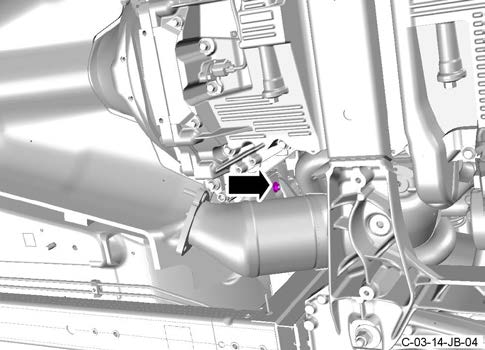 Figure 42
- Install the nut that attaches the heat shield for the front floor, to the body (refer to Figure 43). Torque the nut to 9 Nm.
 Figure 43
WARNING: THE PROPELLER SHAFT IS LARGE. GET THE AID OF ONE MORE PERSON WHEN YOU INSTALL THE PROPELLER SHAFT. IF YOU DO NOT, DAMAGE OR INJURY CAN OCCUR.
CAUTION: BE CAREFUL WHEN YOU INSTALL THE PROPELLER SHAFT. YOU CAN EASILY DAMAGE THE SPLINES IN THE CLUTCH WHEN YOU INSTALL THE PROPELLER SHAFT.
- Carefully install the propeller shaft into the torque tube and engage the splines of the propeller shaft in the clutch (refer to Figure 44).
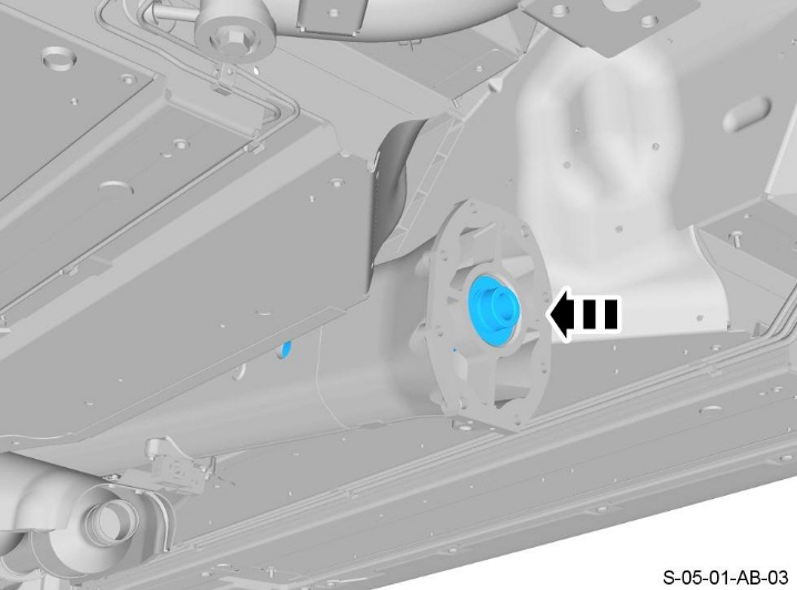 Figure 44
- Install the circlip that keeps the propeller shaft in the torque tube (refer Figure 45).
 Figure 45
Part G – Install the transaxle assembly
- Align the transaxle assembly with the torque tube
- Install six of the eight bolts that attach the transaxle to the torque tube (refer to Figure 46).
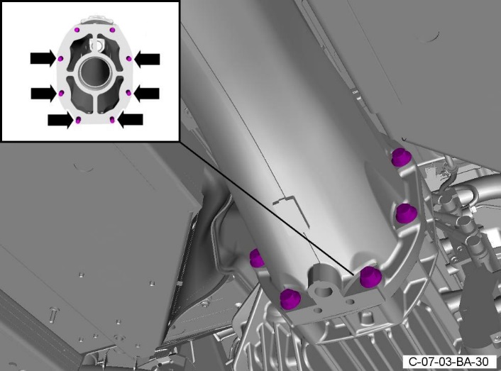 Figure 46
- Put the new bracket assembly (1) for the transmission tube in position. Align the bracket with the two remaining holes in the torque tube (refer to Figure 47).
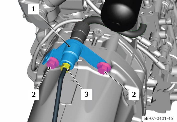 Figure 47
- Install the last two bolts (2) that attach the transaxle to the torque tube.
- Tighten the eight bolts that attach the transaxle to the torque tube to 50 Nm.
- Connect the tube assembly for the slave cylinder (3) to the bracket assembly (1).
- Connect the dry-break connector to the tube assembly for the clutch slave cylinder (refer to Figure 48). Make sure that the locking collar for the connector is in the correct position shown in view A of Figure 49. View B shows a connector that is not correctly connected.
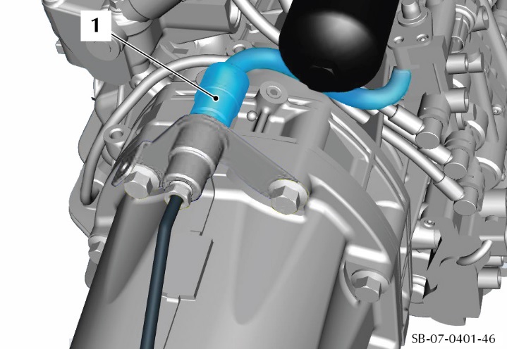 Figure 48
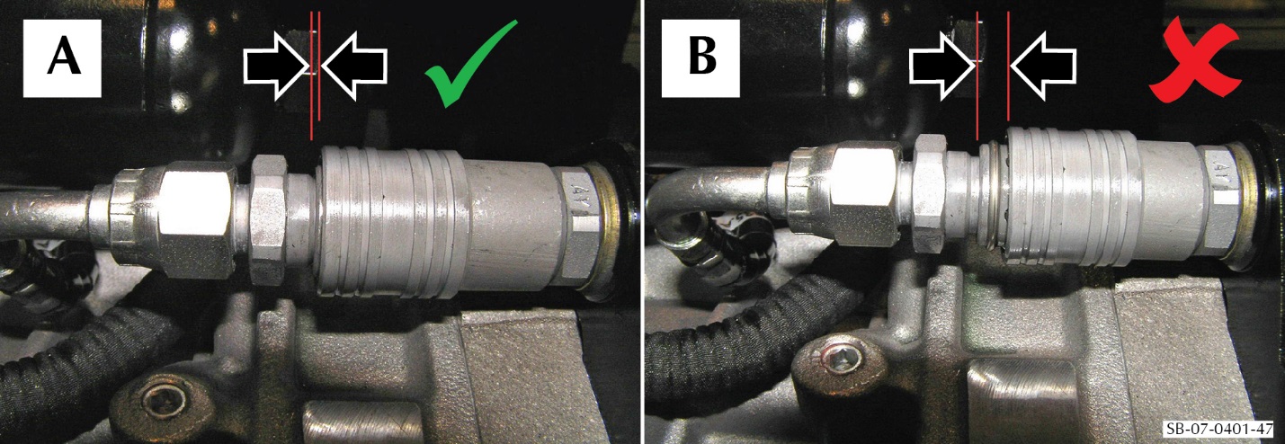 Figure 49
- Use the transmission lift to lift the transaxle and torque tube assembly until you can put the electrical harness into the correct position.
- Connect the electrical connector (6) to the control module (refer to Figure 50).
- Connect the five electrical connectors (5) to the valve block.
- Connect the electrical connector (4) to the ASM pump.
- Install the clip (3) that attaches the electrical harness.
- Install the screws that attach each of the two ground connections (1 and 2) to the transaxle.
 Figure 50
- Use the transmission lift to lift the transaxle sufficiently to install the clip (1) that attaches the electrical harness (2) to the subframe (3) (refer to Figure 51).
 Figure 51
- Put the left mount bracket, with the hydramount attached, in position (refer to Figure 52).
- Install four new bolts to attach the left side mount bracket to the transaxle. Torque the bolts to 63 Nm.
 Figure 52
- Put the mounting bracket for the SportShift fluid reservoir in position. Install the two screws that attach the reservoir mounting bracket to the transaxle mount bracket.
- Put the reservoir (3) in position (refer to Figure 53).
- Put the clamp (2) in position to hold the reservoir (3).
- Install the screw (1) to attach the clamp (2) that attaches the fluid reservoir (3).
 Figure 53
- Put the reservoir hose (1) into position in the two clips
(2) that attach it to the left side mount bracket (refer to Figure 54). Install the reservoir hose into the two clips (1).
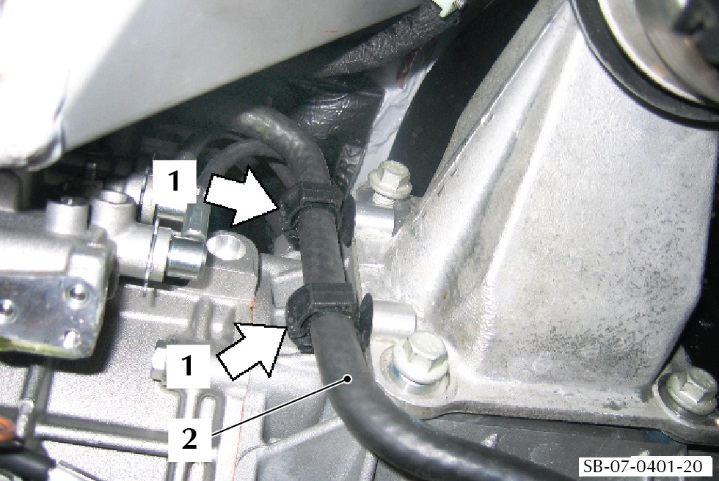 Figure 54
- Put the right mount bracket with the hydramount attached into position (refer to Figure 55).
- Install four new bolts to attach the right side mount bracket to the transaxle. Torque the bolts to 63 Nm.
 Figure 55
- Install the nut that attaches the left side transaxle mount to the rear subframe (refer to Figure 56). Torque the nut to 48 Nm.
 Figure 56
- Install the nut that attaches the right side transaxle mount to the rear subframe (refer to Figure 57). Torque the nut to 48 Nm.
- Remove the transmission lift.
 Figure 57
- Install the breather pipe for the transaxle (refer to Figure 58).
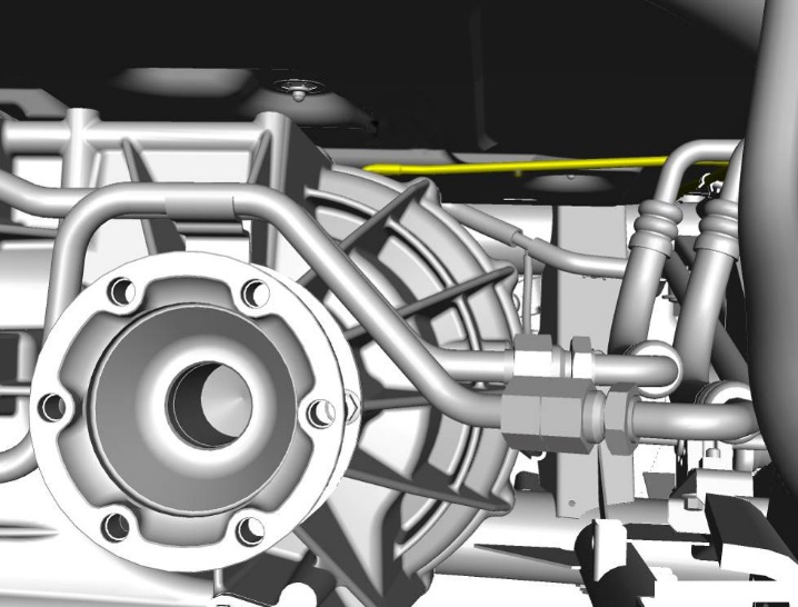 Figure 58
- Put the right-side drive shaft flange in position on the transaxle shaft (refer to Figure 59). Align the marks on the drive shaft flange that you made during step 23.
 Figure 59
- Install the three locking plates and six new Allen head bolts to attach the right drive shaft flange to the transaxle shaft.
- Put the left side drive shaft flange in position on the transaxle shaft (refer to Figure 60). Align the marks on the drive shaft flange that you made during step 23.
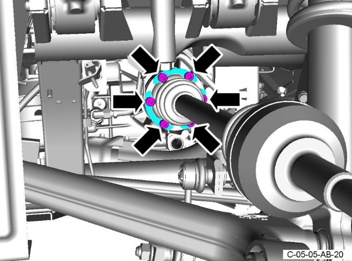 Figure 60
- Install the three locking plates and six new Allen head bolts to attach the left drive shaft flange to the transaxle shaft.
- Install the bolt (1) that attaches the ground cable (2) to the transmission mount bracket (3) (refer to Figure 61).
 Figure 61
- Fill the transaxle with the correct oil (refer to Workshop Manual procedure 07.03.BC). Put the tunnel reinforcement plate in position (refer to Figure 62).
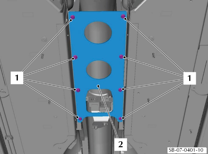 Figure 62
- Install the eight bolts (1) that attach the tunnel reinforcement plate (2) to the body. Torque the eight bolts to 9 Nm.
- Put the tunnel heatshield (2) into position (refer to Figure 63).
 Figure 63
- Install the four bolts and four washers (1) that attach the tunnel heatshield (2) to the body. Torque the four bolts to 23 Nm.
- Install the exhaust centre brace assembly (refer to Figure 64).
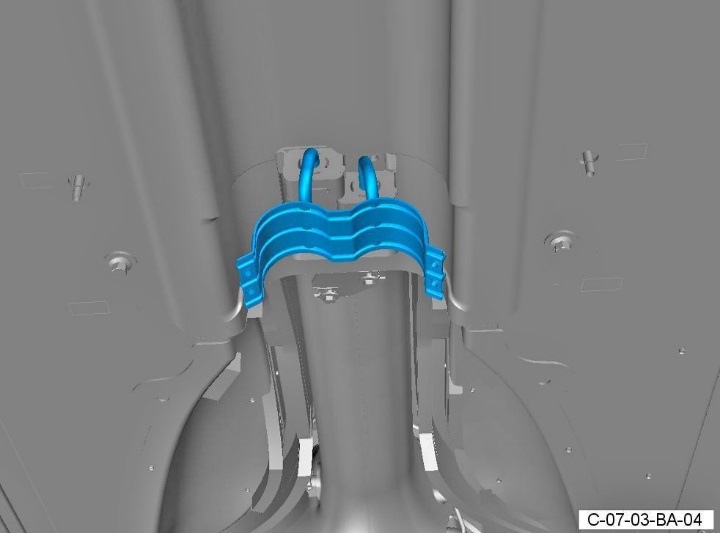 Figure 64
- Put a new sealing ring in position in each joint between the centre pipe and the muffler.
WARNING: THE EXHAUST PIPES ARE HEAVY. GET THE AID OF ONE MORE PERSON WHEN YOU DO THE STEPS THAT FOLLOW.
- Install the centre and rear exhaust pipes as an assembly (refer to Figure 65).
 Figure 65
- Install the four bolts that attach the centre exhaust pipe to the exhaust front mount (refer to Figure 66). Torque the four bolts to 9 Nm.
 Figure 66
- Apply an applicable sealing paste to the joints between the two catalytic converters and the pipe assemblies.
- Move the two clamps (1) into the correct positions on the catalytic converters and pipe assemblies (refer to Figure 67).
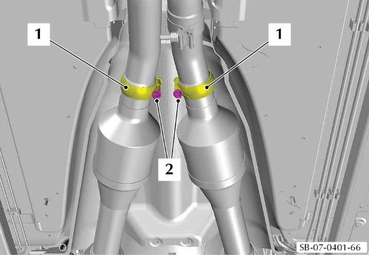 Figure 67
- Tighten the clamp bolt (2) on each of the two clamps (1).
- Install the four bolts and four springs that attach the exhaust centre pipe to the muffler and bypass valve assembly (refer to Figure 68). Torque the four bolts to 30 Nm.
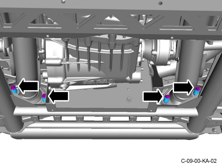 Figure 68
- Hold the cross brace (2) in position (refer to Figure 69).
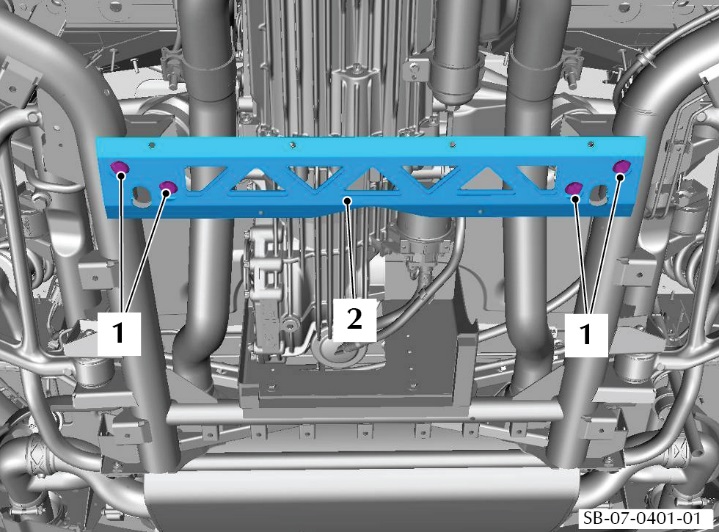 Figure 69
- Install the four screws (1) that attach the cross brace (2). Torque the four bolts to 71 Nm.
- Lower the vehicle.
- Do the battery connect procedure (refer to Workshop Manual procedure 14.01.CA).
- Do the clutch bleed procedure (refer to Workshop Manual procedure 08.00.AE).
- Install the rear undertray (refer to Workshop Manual procedure 01.02.PB)
Warranty Data
Make sure that you submit your claim in less than 24 hours after the work is completed. The records of your claims are used in the reporting process for the Recall Action that Aston Martin need to submit to the National Highway Traffic Safety Administration.
Procedure and Labour Time
| Description | Labour Time |
| Examine the connector for the ASM clutch tube assembly. | 0.05 hours |
| Examine and if necessary replace the Replace the ASM clutch tube assembly. | 6.55 hours |
Part Data
The parts necessary for this repair are avaialbe as a kit. Use the part number 6G33-33-10829 to order this kit. The list below shows the contents of the kit.
Contents of the kit (Part Number 6G33-33-10829)
| Description | Part Number | Quantity |
| Tube assembly, master to slave cylinder. | 6G33-7K502-AA | 1 |
| Bracket assembly, transmission tube | 6G33-7J200-AB | 1 |
| EVO Pipe Kit C, dry break connector | 6G33-7J327-AA | 1 |
| Screw (driveshaft attachment) | 4G43-CD60-AE | 12 |
| Sealing ring (Exhaust) | 4G43-17213-AA | 2 |
| Bolt, M10x25, bracket to transmission | 705355 | 8 |
| Bolt, caliper to knuckle | 4G43-2C564-AB | 4 |
| Nut, rear drive shaft | 6W83-4B423-AA | 2 |
Other necessary materials
| Description | Part Number | Quantity |
| Castrol BOT 270A (Oil, transaxle) (1 Litre bottles) | 6G33-75106-AA/S | 4.5 Litres |
| Pentosin CHF 11S (Sportshift fluid) (1 Litre bottle) | 6G33-19H373-BA | As necessary |
Please Note:
When you have completed this Recall Action, make sure that you make an entry in Section A of the Vehicle Owner’s Guide to show that the procedure is completed.
| If you have any questions related to this Recall Action, please contact: Aston Martin Technical Services on: +44 (0) 1926 644720, email: askamtech@astonmartin.com, or contact your After Sales Manager.
The English version of this Recall Action is written in Simplified Technical English to ASD-STE100™. |
Copy of the Owner Notification Letter
[Date DD Month, YYYY]
[Customer Name]
[Customer Address 1]
[Customer Address 2]
[Customer City/County]
[Customer Country]
IMPORTANT SAFETY RECALL NOTICE RA-07-0023
This notice applies to your vehicle: [INSERT VIN]
Dear [Customer]
Safety Recall Action RA-07-0023 – Connector failure on V8 Vantage 6-Speed SportShift Transmission
Aston Martin has determined that a defect which relates to motor vehicle safety exists on V8 Vantage vehicles that were manufactured from October 2011 thru February 2012 with SportShift 6-speed ASM transmission.
In October 2011, a connector in the hydraulic system for the 6-speed Auto-Shift Manual (ASM) transmission was redesigned. After redesigning the installation for the connector, it was discovered that due to movement in the connector assembly, it is possible in some circumstances for the connector to fail, causing leakage of hydraulic fluid. This would result in malfunction of the clutch system, which could cause a vehicle crash.
A Service Bulletin was issued to repair any vehicle that comes to a Dealer workshop with a leaking connector but we have now decided to repair all vehicles that could be affected.
WHAT WE WILL DO
We will examine the vehicle to check if the Service Bulletin was completed previously. If it was not, the clutch pipe, connector assembly and related brackets will be replaced with parts known to be reliable in operation When you have booked the vehicle in with your Dealer, wherever possible they will endeavour to complete the modification while you wait, to minimise the impact on your time.
WHAT YOU SHOULD DO
Please contact your Aston Martin dealer as soon as possible to arrange a date for the repair. They will be able to fully explain why this Recall Action is necessary. Instructions for making this correction have been sent to your dealer. The labor time necessary to complete this service correction is a maximum of 7 hours. Please ask your dealer if you wish to know how much additional time will be needed to schedule and process your vehicle.
Your Aston Martin dealer is best equipped to obtain parts and provide the service to make sure that your vehicle is corrected as promptly as possible. If, however you take your vehicle to your dealer on the agreed service date and they do not remedy this condition on that date, or within three days, we recommend that you contact Aston Martin Customer Service by calling 1-888923-9988.
If after contacting your dealer and Aston Martin Customer Services, you are still not able to have the safety defect remedied without charge and within a reasonable time, you may wish to write to the Administrator, National Highway Traffic Safety Administration, 1200 New Jersey Avenue, SE, Washington, DC 20590 or call 1-888-327-4236 (TTY: 1-800-424-9153) or go to https://www.safercar.gov.
If you have already had your vehicle repaired due to this problem before receipt of this notice, you may be entitled to reimbursement for any out of pocket costs. For further information, please contact Aston Martin Customer Service by calling 1-888-923-9988.
IF YOU NO LONGER OWN THE VEHICLE
If you have sold or traded your vehicle, please tell us by completing the enclosed Change of Keeper form and returning it to us.
Federal regulations require that any lessor receiving this recall notice must forward a copy of
this notice to the lessee within ten days.
We are sorry to cause inconvenience with this Recall Action. However, this action has been taken in the interest of your safety and continued satisfaction with our products.
Yours sincerely
Phil Eaglesfield
Director, Client Services
Aston Martin Lagonda Limited
Chronology :
In April 2017, we were notified about driveability problems on V8 Vantage Sportshift vehicles. The vehicles were 10,11 and 12.5 model years (manufactured from 12/2010 to 08/2012). We immediately launched an investigation into the issue.
From April 2017 to June 2017, an internal investigation was initiated into the possible cause of driveability and gear-shifting problems. A Service Bulletin to repair a leaking clutch feed pipe was issued on 6-Speed Sportshift. We reviewed the Service Bulletin and it was determined that the failure rate had increased with vehicle age and mileage.
A recommendation was made by the Critical Concerns Review Group (CCRG) to progress the matter to the Recall Committee on 5 June, 2017.
A Recall Committee convened on June 15, 2017 and determined to launch a Recall of all vehicles that still have not had the Service Action completed.
1 Affected Product
Vehicle
| MAKE | MODEL | YEAR |
| ASTON MARTIN | V8 VANTAGE | 2012 |
11 Associated Documents
Manufacturer Notices(to Dealers,etc)
RCMN-17V390-6759.pdf 4489.036KB
 Loading...
Recall Acknowledgement
RCAK-17V390-3167.pdf 281.259KB
Loading...
Recall Quarterly Report #2, 2017-4
RCLQRT-17V390-6063.PDF 214.612KB
Loading...
Recall 573 Report
RCLRPT-17V390-5686.pdf 217.839KB
Loading...
Manufacturer Notices(to Dealers,etc) – Safety Bulletin – Reference Number: N172105680 Release Date: July 2017
RCMN-17V390-7804.pdf 4620.854KB
Loading...
Recall Quarterly Report #1, 2017-3
RCLQRT-17V390-0513.PDF 214.511KB
Loading...
Owner Notification Letter(Part 577)
RCONL-17V390-2995.pdf 253.049KB
Loading...
Recall Quarterly Report #3, 2018-1
RCLQRT-17V390-5720.PDF 214.712KB
Loading...
Recall Quarterly Report #4, 2018-2
RCLQRT-17V390-0325.PDF 214.803KB
Loading...
Recall Quarterly Report #5, 2018-3
RCLQRT-17V390-2388.PDF 214.908KB
Loading...
Recall Quarterly Report #6, 2018-4
RCLQRT-17V390-9170.PDF 211.619KB
Loading...
Latest Recalls Documents
For the Latest and Most Recent Recalls Information Visit the link below…
https://www-odi.nhtsa.dot.gov/acms/cs/documentList.xhtml?docId=17V390&docType=RCL
- Pentosin ATF 6 has been specially developed with reduced viscosity to optimize the performance of specified 6-speed ZF automatic transmissions
- It is essential that the correct ATF is specified in order to ensure the transmission performs to its potential, providing efficient and reliable operation throughout its lifetime
- Pentosin ATF 6 has been developed to deliver good friction control, excellent durability and oxidation control which delivers long oil life with proven performance
- Formulated specifically for select Aston Martin, Audi, Bentley, BMW, Jaguar, Land Rover, Maserati, and Rolls Royce vehicles that use select ZF 6-speed automatic transmissions
- 5 liter jug; sold individually
- FOR USE IN 95% of ATF VEHICLES INCLUDING MOST CVTs in operation with US registered light duty applications
- HIGH PERFORMANCE CONDITIONING AGENTS prolong seal elasticity to prevent leaks
- IMPROVE DURABILITY & TRANSMISSION LIFE with anti-wear technology to avoid costly repairs
- ENHANCED HIGH & LOW TEMP PERFORMANCE supports transmission fluid in all weather situations
- FULL SYNTHETIC FORMULA protects against engine breakdown better than conventional fluids
- The information below is per-pack only
- SUITABLE FOR USE IN 95% of ATF VEHICLES in operation with US registered light duty applications.
- HIGH PERFORMANCE CONDITIONING AGENTS prolong seal elasticity to prevent leaks
- IMPROVE DURABILITY & TRANSMISSION LIFE with anti-wear technology to avoid costly repairs, Superior anti-shudder performance
- ENHANCED HIGH & LOW TEMP PERFORMANCE supports transmission fluid in all weather situations

- WIDEST SPECIFICATION RANGE - Compatible with FORD XL-12 Case Fluid, BMW LT 71141, Allison TES 295, TES 389, MERCON V, Dexron VI, JEEP ATF 3, ATF 4, HONDA DW1, KIA SP-III/ IV, Mazda ATF MIII / MV, Nissan Matic D/J/K/S/W - See complete spec pictures of spec sheet
- FILL FOR LIFE in passenger cars, SUVs and light duty trucks; High shear and thermal stability make this fluid extremely long lasting; 300,000+ mile drain on passenger cars and SUVs; 100,000 miles for heavy duty pickup trucks
- HEAVY DUTY DURABILITY – High load carrying capacity, high film strength, and transmission protection make this product ideal for heavy duty applications such as diesel trucks, towing, hauling, and general high torque applications
- OEM GRADE – Meets or exceeds the specification and performance requirements when compared with OEM fluids from most manufacturers
- KEY PERFORMANCE METRICS – Highly efficient torque transfer; Lower transmission operating temperature; Superb protection for key transmission parts; Excellent seal maintenance; Smooth rapid and precise shifting without slipping

- 6 x 1L Automatic Transmission Fluid (ATF)
- Part # 20032
- Made in Germany.
- Please see description below for compatible cars.
- Made in Korea by HYUNDAI
- Suitable for multi vehicles (Not only HYUNDAI / KIA)
- Provide good wear control to maintain equipment life.
- Provide excellent protection against rust and corrosion.
- Provides thermal and oxidative stability.

- Automatic Transmission Fluid (1 Liter)
- (ATF 4134) MBZ Approval: 236.14
- NOTE: This is a high performance fluid designed to optimize shifting performance. For use with the 5-Speed 722.6 & 7-Speed 722.9 Transmission.
- Mercedes part# 001 989 68 03 13, Genuine Mercedes
- Please see FITMENT CHART below, under PRODUCT DESCRIPTION.

- Pentosin ATF 134 FE was developed to further optimize gearbox efficiency of latest generation Mercedes-Benz 7G Tronic Plus automatic transmissions
- Fluid meets Mercedes spec. 236.15 and is OE approved for Mercedes Benz 7-speed transmissions produced after June 2010 (MB OE # 001-989-78-03)
- Lowest viscosity ATF available provides impressive fuel economy potential and low-temperature behavior
- Blue in color - not backwards compatible with earlier red Mercedes spec fluids used in prior 7-speed automatic transmissions; 5 liter jug - sold individually
- For select vehicles: Mercedes-Benz: 2010-15 C250, 2010-16 C300, 2010-15 C350, 2015 C400, 2016 C450 AMG, 2010-20 C63 AMG, 2015-20 C63 AMG S, 2010-14 CL550, 2010-14 CL63 AMG, 2015-16 CLS400, 2010-16 CLS550, 2010-14 CLS63 AMG, 2014-18 CLS63 AMG S
- Specially developed
- Provides excellent lubrication under high load, high heat
- Factory filled ATF+4
- Genuine OEM Chrysler fluid
- Fill for life quality fluid

- Formulated with full-synthetic base stocks and advanced additive technology to meet the challenging demands of automatic transmissions.
- Enhanced anti-shudder protection for smooth shifting and maximum power transfer
- Developed with anti-wear technology to help improve transmission durability
- Engineered with a proprietary blend of base oils and advanced additives to provide better oil flow at low temperatures and greater film protection at higher temperatures
Last update on 2024-03-24 / Affiliate links / Images from Amazon Product Advertising API
This product presentation was made with AAWP plugin.
SEOCONTENT-START
August 18, 2017 IMPORTANT SAFETY RECALL NOTICE NHTSA Recall Ref 17V-390 This notice applies to your vehicle Dea Safety Recall Action RA-07-0023 – Connector failure on VB Vantage 6-Speed SportShift Transmission This notice is sent to you in accordance with the requirements of the National Traffic and Motor Vehicle Safety Act. Aston Martin has determined that a defect which relates to motor vehicle safety exists on VB Vantage vehicles that were manufactured from October 2011 thru November 2011 with SportShift 6-speed ASM transmission. In October 2011, a connector in the hydraulic system for the 6-speed Auto-Shift Manual (ASM) transmission was redesigned. After redesigning the installation for the connector, it was discovered that due to movement in the connector assembly, it is possible in some circumstances for the connector to fail, causing leakage of hydraulic fluid. This would result in malfunction of the clutch system, which could cause a vehicle crash. A Service Bulletin was issued to repair any vehicle that comes to a Dealer workshop with a leaking connector but we have now decided to repair all vehicles that could be affected. WHAT WE WILL DO We will examine the vehicle to check if the Service Bulletin was completed previously. If it was not, the clutch pipe, connector assembly and related brackets will be replaced with parts known to be reliable in operation. When you have booked the vehicle in with your Dealer, wherever possible they will endeavour to complete the modification while you wait, to minimize the impact on your time. WHAT YOU SHOULD DO Please contact your Aston Martin dealer as soon as possible to arrange a date for the repair. They will be able to fully explain why this Recall Action is necessary. Instructions for making this correction have been sent to your dealer. The labor time necessary to complete this service correction is a maximum of 7 hours. Please ask your dealer if you wish to know how much additional time will be needed to schedule and process your vehicle. Your Aston Martin dealer is best equipped to obtain parts and provide the service to make sure that your vehicle is corrected as promptly as possible. If, however you take your vehicle to your dealer on the agreed service date and they do not remedy this condition on that date, or within RA-07-0023 – Customer Letter Fed.docx Page 1 of 2 V23 1 three days, we recommend that you contact Aston Martin Customer Service by calling 1-888- 923-9988. If after contacting your dealer and Aston Martin Customer Services, you are still not able to have the safety defect remedied without charge and within a reasonable time, you may wish to write to the Administrator, National Highway Traffic Safety Administration, 1200 New Jersey Avenue, SE, Washington, DC 20590 or call 1-888-327-4236 (TTY: 1-800-424-9153) or go to http://www.safercar.gov. If you have already had your vehicle repaired due to this problem before receipt of this notice, you may be entitled to reimbursement for any out of pocket costs. For further information, please contact Aston Martin Customer Service by calling 1-888-923-9988. IF YOU NO LONGER OWN THE VEHICLE If you have sold or traded your vehicle, please tell us by completing the enclosed Change of Keeper form and returning it to us. Federal regulations require that any lessor receiving this recall notice must forward a copy of this notice to the lessee within ten days. We are sorry to cause inconvenience with this Recall Action. However, this action has been taken in the interest of your safety and continued satisfaction with our products. Yours sincerely Phil Eaglesfield Director, Client Services Aston Martin Lagonda Limited RA-07-0023 • Customer Letter Fed.docx Page 2 of 2
**************************************************************************************************************
ASTON MARTIN CLIENT SERVICES 6 July, 2017 Page 1 of 27 SAF E T Y RECAL L ACTION Reference number: RA-07-0023 Issued: 6 July, 2017 Subject: Connector failure on V8 Vantage 6-Speed SportShift Transmission Model(s): V8 Vantage with 6-Speed SportShift Transmission VIN range: Refer to the separately published list of VINs Applicable to: All Dealers (Not USA) Distribute to: After Sales Manager Executive Manager Service Manager Sales Manager Warranty Staff Technician(s) Parts Staff Attached Documents: 1. Copy of the Owner Notification letter for vehicles in RA-07-0023. 2. Copy of the Change of Keeper or Address form. Reason for this Recall Action This Recall Action is applicable to the vehicles that follow: • V8 Vantage Coupe and Roadster with 6-Speed “SportShift” transmission manufactured from October – November 2011. Aston Martin has determined that a defect which relates to motor vehicle safety exists on a range of V8 Vantage vehicles that were manufactured from September thru November 2011. From VIN C15849, the 6-speed ASM transmission installed on V8 Vantage, has a different design of connector between the pipe for the clutch fluid and the ASM (Auto-Shift Manual) system. It is possible that this connector can fail and cause loss of the clutch fluid. Detailed description of the problem If the hydraulic fluid leaks, the level will go down. As the fluid level goes down, the following can occur: • The driver may see signs of fluid below the vehicle or underneath on the ground. • At start-up, an “Unable to select gears” warning will display in the driver’s display and the transmission will not change from Neutral or Park into a gear. The driver will be unable to move the vehicle. • While driving, an “Unable to select gears” warning will flash and the driver can continue in the same gear until they choose a place to stop. In this condition, if the driver operates the brakes, the engine can be stalled as the vehicle comes to a stop. • If, in the case above there is sufficient pressure remaining in the hydraulic system, the transmission will select emergency neutral as the vehicle comes to a stop. Note: It is possible that a vehicle has had the connector replaced before by Service Bulletin SB-07-0401. Refer to Part A of this procedure. If the installed connector is type B shown in Figure 3, you do not need to do this workshop procedure. To correct the problem To correct this problem, you must: • Do a check to see if Service Bulletin SB-07-0401 has been completed on the vehicle. • If necessary, install a new connector and support bracket. SAFETY RECALL ACTION RA-07-0023 6 July, 2017 Page 2 of 27 The full list of VINs for the affected vehicles is on the DCS portal as an attachment to this Recall Action document. PLEASE DO A CHECK OF ALL VEHICLES THAT ARE IN THE AFFECTED VIN LIST Communications We will write to every owner directly to tell them about this Safety Recall Action. A copy of the letter is attached at the end of this Recall Action for your information. There is also a copy of the “Change of Keeper’s Address or Ownership” form. When the Owner calls to make an appointment, briefly describe the remedial work which will be done to the Owner’s vehicle and fully explain the reason for this work. Tell the owner that the repair will be done at no cost to them. Service Reception Desk – Checks you must do before you book the vehicle in. When you make a reservation for a Customer that you confirm the name and contact details are correct in Aston Martin’s records. To do this, please do the steps that follow: 1. Enter the vehicle’s 6-digit chassis number into DCS (amdealers.com) and click “Validate” (refer to Figure 1). Figure 1 2. Make sure that the vehicle details are correct. If the current owner is correct, no action is necessary. 3. Make sure that the Customer name is correct. If the data is correct, then no action is necessary. 4. To update the Customer details, use the search feature to find the customer in your Synergy database (refer to Figure 2). Figure 2 Note: The Customer record and updated details must have been entered into Synergy before you try to transfer the ownership in DCS. 5. If the correct Customer shows, click “confirm”. SAFETY RECALL ACTION RA-07-0023 6 July, 2017 Page 3 of 27 6. If the correct Customer details do not show, click “add new”. Before you start work Log on to the Online Dealer Warranty (ODW) system. Do the steps that follow: 1. Select the Warranty Live screen (Outstanding Campaigns Status). 2. Download the attached VIN list from the DCS Portal and do a check of the VINs in your control. 3. Find out if there are other open Service Actions (SAs) or Recall Actions (RAs) for the vehicles in the list. 4. List the SAs and RAs and plan the work so that the Owner only needs to come to your Dealership once. Note: The ODW system operates in real-time. Thus, the online condition shows only the newest Dealer Warranty Claim submissions. Workshop Procedure This Workshop Procedure has the parts that follow: • Part A – Inspect the connector for the clutch fluid line. • Part B – Remove the transaxle assembly. • Part C – Remove the torque tube assembly. • Part D – Change the supply tube assembly for the concentric slave cylinder. • Part E – Change the hose for the dry break connector. • Part F – Install the torque tube assembly. • Part G – Install the transaxle assembly. Part A – Inspect the connector for the clutch fluid line 1. Raise the vehicle and make it safe. 2. Use an endoscope to examine the connector between the clutch fluid tube and the transmission. 3. If the connector is the same as type “A” shown in Figure 3, continue from Part B. 4. If the connector is the same as type “B” shown in Figure 3, you do not need to do more work. Faulty Connector New Connector Figure 3 SAFETY RECALL ACTION RA-07-0023 6 July, 2017 Page 4 of 27 Part B – Remove the transaxle assembly WARNING: THE EXHAUST SYTEM WILL BE VERY HOT AFTER OPERATION AND CAN BURN YOU. LET THE EXHAUST SYSTEM BECOME COOL BEFORE YOU DO WORK ON THE SYSTEM. 5. Make sure that the transmission is in neutral gear. 6. Use an applicable strap to attach the vehicle to the lift. 7. Do the battery disconnect procedure (refer to Workshop Manual procedure 14.01.CA). 8. Lift the vehicle and make it safe. 9. Drain the oil from the transaxle (refer to Workshop Manual procedure 07.03.BC). 10. Hold the cross brace (2). Remove the four screws (1) that attach the cross brace (2) and remove the cross brace (2) (refer to Figure 4). Figure 4 11. Remove the four bolts and collect the four springs that attach the exhaust centre pipe to the muffler and bypass valve assembly (refer to Figure 5). Figure 5 SAFETY RECALL ACTION RA-07-0023 6 July, 2017 Page 5 of 27 12. Loosen the two bolts on the clamps that attach the catalytic converter and pipe assemblies to the centre exhaust pipe (refer to Figure 6). Figure 6 13. Move the two clamps on the catalytic converter and pipe assemblies away from the centre exhaust pipe (refer to Figure 7). Figure 7 14. Put an applicable support below the centre exhaust pipe. WARNING: THE EXHAUST PIPES ARE HEAVY. GET THE AID OF ONE MORE PERSON WHEN YOU DO THE STEPS THAT FOLLOW. 15. Remove the four attachment bolts for the centre exhaust mounting (refer to Figure 8). Figure 8 16. Loosen the two clamp nuts and release the centre pipe from the two catalysts. SAFETY RECALL ACTION RA-07-0023 6 July, 2017 Page 6 of 27 17. Remove the centre pipe and the rear exhaust pipes as an assembly (refer to Figure 9). Figure 9 18. Remove and discard the two sealing rings (refer to Figure 10). Figure 10 19. Remove the exhaust centre brace assembly (refer to Figure 11). Figure 11 SAFETY RECALL ACTION RA-07-0023 6 July, 2017 Page 7 of 27 20. Remove the four bolts and four washers (1) that attach the tunnel heatshield (2) to the body. Remove the heatshield (2) (refer to Figure 12). Figure 12 21. Remove the eight bolts (1) that attach the tunnel reinforcement plate (2) to the body and remove the plate (2) (refer to Figure 13). Figure 13 22. Remove the bolt (1) that attaches the ground cable (2) to the transmission mount bracket (3) and move the ground cable (2) away (refer to Figure 14). Figure 14 23. Make a mark on each of the two drive shafts to differential flanges for alignment during assembly. SAFETY RECALL ACTION RA-07-0023 6 July, 2017 Page 8 of 27 24. Remove and discard the six Allen head bolts that attach the left drive shaft flange to the transaxle. Collect the three locking plates from the drive shaft flange (refer to Figure 15). Figure 15 25. Remove and discard the six Allen-head bolts that attach the right drive shaft flange to the transaxle. Collect the three locking plates from the drive shaft flange (refer to Figure 16). Figure 16 26. Disconnect the breather pipe from the transaxle and move the pipe away (refer to Figure 17). Figure 17 27. Put a transmission lift below the transaxle. 28. Adjust the height of the transmission lift to hold the weight of the transaxle. SAFETY RECALL ACTION RA-07-0023 6 July, 2017 Page 9 of 27 29. Remove the nut that attaches the right-side transaxle mount to the rear subframe (refer to Figure 18). Figure 18 30. Remove the nut that attaches the left-side transaxle mount to the rear subframe (refer to Figure 19). Figure 19 31. Remove and discard the four bolts that attach the right-side transaxle mount bracket to the transaxle. Remove the mount bracket with the hydramount attached (refer to Figure 20). Figure 20 SAFETY RECALL ACTION RA-07-0023 6 July, 2017 Page 10 of 27 32. Release the reservoir hose (1) from the two clips (2) that attach it to the left-side mount bracket (refer to Figure 21). Figure 21 33. Remove the screw (1) to release the clamp (2) that attaches the fluid reservoir (3) (refer to Figure 22). Figure 22 34. Remove the clamp (2) and move the reservoir (3) away. 35. Remove the two screws that attach the reservoir mounting bracket to the transaxle mount bracket and remove the reservoir mounting bracket. 36. Remove and discard the four bolts that attach the left side mount bracket to the transaxle. Remove the mount bracket with the hydramount attached (refer to Figure 23). Figure 23 37. Release the drive shafts from the transaxle and move them away. SAFETY RECALL ACTION RA-07-0023 6 July, 2017 Page 11 of 27 38. Use the transmission lift to lower the transaxle sufficiently to get access to the clip (1) that attaches the electrical harness (2) to the subframe (3). Release the clip (1) from the subframe (2) (refer to Figure 24). Figure 24 39. Lower the transaxle to approximately 420 mm from the installed position and use applicable straps to hold it onto the hydraulic lift. 40. Remove the clip (1) (if it is still installed) that holds the clutch hose connector (2) together at the joint between the transaxle and the torque tube (refer to Figure 25). Figure 25 41. Disconnect the hose (2). 42. Remove the screw that attaches each of the two ground connections (1 and 2) to the transaxle (refer to Figure 26). Figure 26 43. Release the clip (3) that attaches the electrical harness. 44. Disconnect the electrical connector (4) from the ASM pump. 45. Disconnect the five electrical connectors (5) from the valve block. 46. Disconnect the electrical connector (6) from the control module. 47. Move the electrical harness away from the transaxle. 48. Put an applicable support in position to hold the torque tube. 49. Use applicable straps to attach the torque tube to the transmission lift. WARNING: THE TRANSAXLE ASSEMBLY IS VERY HEAVY. GET THE AID OF ONE MORE PERSON WHEN YOU MOVE THE TRANSAXLE. IF YOU DO NOT, PERSONAL INJURY CAN OCCUR. SAFETY RECALL ACTION RA-07-0023 6 July, 2017 Page 12 of 27 50. Remove the eight bolts that attach the transaxle to the torque tube (refer to Figure 27). Figure 27 51. Move the transaxle rearward to give clearance between the torque tube and the transaxle. 52. Remove the transaxle. Part C – Remove the torque tube assembly 53. Remove the circlip that keeps the propeller shaft in the torque tube (refer Figure 28). Figure 28 CAUTION: THE PROPELLER SHAFT IS LARGE. GET THE AID OF ONE MORE PERSON WHEN YOU REMOVE THE PROPELLER SHAFT. IF YOU DO NOT, DAMAGE CAN OCCUR. CAUTION: BE CAREFUL WHEN YOU REMOVE THE PROPELLER SHAFT. YOU CAN EASILY DAMAGE THE SPLINES IN THE CLUTCH WHEN YOU REMOVE THE PROPELLER SHAFT. 54. Carefully remove the propeller shaft from the torque tube (refer to Figure 29). Figure 29 SAFETY RECALL ACTION RA-07-0023 6 July, 2017 Page 13 of 27 55. Remove the nut that attaches the heat shield for the front floor to the body (refer to Figure 30). Figure 30 56. Remove the nut that attaches the heat shield for the front floor to the body Figure 31. Figure 31 57. Remove the two screws (1) that attach the front of the heat shield (2) for the front floor to the torque tube (refer to Figure 32). Figure 32 58. Remove the two screws (3) that attach the rear of the heat shield (2) to the torque tube and remove the heat shield (2). SAFETY RECALL ACTION RA-07-0023 6 July, 2017 Page 14 of 27 59. Disconnect the electrical connector from the speed sensor for the propeller shaft (refer to Figure 33). Figure 33 60. Use the transmission jack to lower the rear end of the torque tube until you can get access to the 16 torque tube attachment bolts. 61. Remove the 16 bolts that attach the torque tube to the engine and remove the torque tube (refer to Figure 34). Figure 34 WARNING: THE TORQUE TUBE IS LARGE AND HEAVY. GET THE AID OF ONE MORE PERSON WHEN YOU REMOVE THE TORQUE TUBE. IF YOU DO NOT, PERSONAL INJURY CAN OCCUR. 62. Remove the torque tube. Part D – Change the supply tube assembly for the concentric slave cylinder 63. Remove the clip (1) that attaches the connector (2) for the clutch fluid tube assembly (tube assembly) to the concentric slave cylinder (3) (cylinder) (refer to Figure 35). SAFETY RECALL ACTION RA-07-0023 6 July, 2017 Page 15 of 27 64. Disconnect the tube assembly (2) from the cylinder (3) (refer to Figure 35). Figure 35 65. Remove the screw (1) that attaches the attachment bracket (2) for the tube assembly (3) to the torque tube (refer to Figure 36). Figure 36 66. Release the tube assembly from the clips that attach it to the torque tube. 67. Discard the tube assembly. 68. Install the new tube assembly (refer to Part Data) into the clips on the torque tube. 69. Connect the tube assembly (2) to the concentric slave cylinder (3) (refer to Figure 37). Figure 37 70. Install a new clip (1) to attach the tube assembly (2) to the concentric slave cylinder (3). SAFETY RECALL ACTION RA-07-0023 6 July, 2017 Page 16 of 27 Part E – Change the hose for the dry break connector 71. On the transaxle assembly, remove the clip (1) that attaches the clutch fluid hose (2) into the valve block (3) (refer to Figure 38). Figure 38 72. Disconnect the clutch fluid hose (2) from the valve block (3). 73. Discard the clutch fluid hose (2). 74. Install the new hose (2) from the EVO pipe kit C (refer to Part Data). 75. Install the new retaining clip (1) to hold the hose (2) into the valve block (3). Part F – Install the torque tube assembly WARNING: THE TORQUE TUBE IS LARGE AND HEAVY. GET THE AID OF ONE MORE PERSON WHEN YOU INSTALL THE TORQUE TUBE. IF YOU DO NOT, PERSONAL INJURY CAN OCCUR. 76. Clean the mating faces between the torque tube and the engine. 77. Align the torque tube assembly with the engine. 78. Install the 16 bolts that attach the torque tube assembly to the engine (refer to Figure 39). Figure 39 79. Torque the 16 bolts to 50 Nm. 80. Connect the electrical connector to the speed sensor for the propeller shaft (refer to Figure 40). Figure 40 SAFETY RECALL ACTION RA-07-0023 6 July, 2017 Page 17 of 27 81. Put the heat shield (2) into position (refer to Figure 41). Figure 41 82. Install the two screws (3) that attach the rear of the heat shield (2) to the torque tube. Torque the two screws to 9 Nm. 83. Install the two screws (1) that attach the front of the heat shield (2) to the torque tube. Torque the two screws to 9 Nm. 84. Install the nut that attaches the heat shield for the front floor to the body (refer to Figure 42). Torque the nut to 9 Nm. Figure 42 85. Install the nut that attaches the heat shield for the front floor, to the body (refer to Figure 43). Torque the nut to 9 Nm. Figure 43 WARNING: THE PROPELLER SHAFT IS LARGE. GET THE AID OF ONE MORE PERSON WHEN YOU INSTALL THE PROPELLER SHAFT. IF YOU DO NOT, DAMAGE OR INJURY CAN OCCUR. CAUTION: BE CAREFUL WHEN YOU INSTALL THE PROPELLER SHAFT. YOU CAN EASILY DAMAGE THE SPLINES IN THE CLUTCH WHEN YOU INSTALL THE PROPELLER SHAFT. SAFETY RECALL ACTION RA-07-0023 6 July, 2017 Page 18 of 27 86. Carefully install the propeller shaft into the torque tube and engage the splines of the propeller shaft in the clutch (refer to Figure 44). Figure 44 87. Install the circlip that keeps the propeller shaft in the torque tube (refer Figure 45). Figure 45 Part G – Install the transaxle assembly 88. Align the transaxle assembly with the torque tube 89. Install six of the eight bolts that attach the transaxle to the torque tube (refer to Figure 46). Figure 46 SAFETY RECALL ACTION RA-07-0023 6 July, 2017 Page 19 of 27 90. Put the new bracket assembly (1) for the transmission tube in position. Align the bracket with the two remaining holes in the torque tube (refer to Figure 47). Figure 47 91. Install the last two bolts (2) that attach the transaxle to the torque tube. 92. Tighten the eight bolts that attach the transaxle to the torque tube to 50 Nm. 93. Connect the tube assembly for the slave cylinder (3) to the bracket assembly (1). 94. Connect the dry-break connector to the tube assembly for the clutch slave cylinder (refer to Figure 48). Make sure that the locking collar for the connector is in the correct position shown in view A of Figure 49. View B shows a connector that is not correctly connected. Figure 48 Figure 49 95. Use the transmission lift to lift the transaxle and torque tube assembly until you can put the electrical harness into the correct position. SAFETY RECALL ACTION RA-07-0023 6 July, 2017 Page 20 of 27 96. Connect the electrical connector (6) to the control module (refer to Figure 50). Figure 50 97. Connect the five electrical connectors (5) to the valve block. 98. Connect the electrical connector (4) to the ASM pump. 99. Install the clip (3) that attaches the electrical harness. 100. Install the screws that attach each of the two ground connections (1 and 2) to the transaxle. 101. Use the transmission lift to lift the transaxle sufficiently to install the clip (1) that attaches the electrical harness (2) to the subframe (3) (refer to Figure 51). Figure 51 102. Put the left mount bracket, with the hydramount attached, in position (refer to Figure 52). Figure 52 103. Install four new bolts to attach the left side mount bracket to the transaxle. Torque the bolts to 63 Nm. 104. Put the mounting bracket for the SportShift fluid reservoir in position. Install the two screws that attach the reservoir mounting bracket to the transaxle mount bracket. SAFETY RECALL ACTION RA-07-0023 6 July, 2017 Page 21 of 27 105. Put the reservoir (3) in position (refer to Figure 53). Figure 53 106. Put the clamp (2) in position to hold the reservoir (3). 107. Install the screw (1) to attach the clamp (2) that attaches the fluid reservoir (3). 108. Put the reservoir hose (1) into position in the two clips (2) that attach it to the left side mount bracket (refer to Figure 54). Install the reservoir hose into the two clips (1). Figure 54 109. Put the right mount bracket with the hydramount attached into position (refer to Figure 55). Figure 55 110. Install four new bolts to attach the right side mount bracket to the transaxle. Torque the bolts to 63 Nm. SAFETY RECALL ACTION RA-07-0023 6 July, 2017 Page 22 of 27 111. Install the nut that attaches the left side transaxle mount to the rear subframe (refer to Figure 56). Torque the nut to 48 Nm. Figure 56 112. Install the nut that attaches the right side transaxle mount to the rear subframe (refer to Figure 57). Torque the nut to 48 Nm. Figure 57 113. Remove the transmission lift. 114. Install the breather pipe for the transaxle (refer to Figure 58). Figure 58 SAFETY RECALL ACTION RA-07-0023 6 July, 2017 Page 23 of 27 115. Put the right-side drive shaft flange in position on the transaxle shaft (refer to Figure 59). Align the marks on the drive shaft flange that you made during step 23. Figure 59 116. Install the three locking plates and six new Allen head bolts to attach the right drive shaft flange to the transaxle shaft. 117. Put the left side drive shaft flange in position on the transaxle shaft (refer to Figure 60). Align the marks on the drive shaft flange that you made during step 23. Figure 60 118. Install the three locking plates and six new Allen head bolts to attach the left drive shaft flange to the transaxle shaft. 119. Install the bolt (1) that attaches the ground cable (2) to the transmission mount bracket (3) (refer to Figure 61). Figure 61 120. Fill the transaxle with the correct oil (refer to Workshop Manual procedure 07.03.BC). SAFETY RECALL ACTION RA-07-0023 6 July, 2017 Page 24 of 27 121. Put the tunnel reinforcement plate in position (refer to Figure 62). Figure 62 122. Install the eight bolts (1) that attach the tunnel reinforcement plate (2) to the body. Torque the eight bolts to 9 Nm. 123. Put the tunnel heatshield (2) into position (refer to Figure 63). Figure 63 124. Install the four bolts and four washers (1) that attach the tunnel heatshield (2) to the body. Torque the four bolts to 23 Nm. 125. Install the exhaust centre brace assembly (refer to Figure 64). Figure 64 126. Put a new sealing ring in position in each joint between the centre pipe and the muffler. WARNING: THE EXHAUST PIPES ARE HEAVY. GET THE AID OF ONE MORE PERSON WHEN YOU DO THE STEPS THAT FOLLOW. SAFETY RECALL ACTION RA-07-0023 6 July, 2017 Page 25 of 27 127. Install the centre and rear exhaust pipes as an assembly (refer to Figure 65). Figure 65 128. Install the four bolts that attach the centre exhaust pipe to the exhaust front mount (refer to Figure 66). Torque the four bolts to 9 Nm. Figure 66 129. Apply an applicable sealing paste to the joints between the two catalytic converters and the pipe assemblies. 130. Move the two clamps (1) into the correct positions on the catalytic converters and pipe assemblies (refer to Figure 67). Figure 67 131. Tighten the clamp bolt (2) on each of the two clamps (1). SAFETY RECALL ACTION RA-07-0023 6 July, 2017 Page 26 of 27 132. Install the four bolts and four springs that attach the exhaust centre pipe to the muffler and bypass valve assembly (refer to Figure 68). Torque the four bolts to 30 Nm. Figure 68 133. Hold the cross brace (2) in position (refer to Figure 69). Figure 69 134. Install the four screws (1) that attach the cross brace (2). Torque the four bolts to 71 Nm. 135. Lower the vehicle. 136. Do the battery connect procedure (refer to Workshop Manual procedure 14.01.CA). 137. Do the clutch bleed procedure (refer to Workshop Manual procedure 08.00.AE). 138. Install the rear undertray (refer to Workshop Manual procedure 01.02.PB) Warranty Data Make sure that you submit your claim in less than 24 hours after the work is completed. Procedure and Labour Time Description Labour Time Examine the connector for the ASM clutch tube assembly. 0.05 hours Examine and if necessary replace the Replace the ASM clutch tube assembly. 6.55 hours Part Data The parts necessary for this repair are avaialbe as a kit. Use the part number 6G33-33-10829 to order this kit. The list below shows the contents of the kit. SAFETY RECALL ACTION RA-07-0023 6 July, 2017 Page 27 of 27 Contents of the kit (Part Number 6G33-33-10829) Description Part Number Quantity Tube assembly, master to slave cylinder. 6G33-7K502-AA 1 Bracket assembly, transmission tube 6G33-7J200-AB 1 EVO Pipe Kit C, dry break connector 6G33-7J327-AA 1 Screw (driveshaft attachment) 4G43-CD60-AE 12 Sealing ring (Exhaust) 4G43-17213-AA 2 Bolt, M10x25, bracket to transmission 705355 8 Bolt, caliper to knuckle 4G43-2C564-AB 4 Nut, rear drive shaft 6W83-4B423-AA 2 Other necessary materials Description Part Number Quantity Castrol BOT 270A (Oil, transaxle) (1 Litre bottles) 6G33-75106-AA/S 4.5 Litres Pentosin CHF 11S (Sportshift fluid) (1 Litre bottle) 6G33-19H373-BA As necessary Please Note: When you have completed this Recall Action, make sure that you make an entry in Section A of the Vehicle Owner’s Guide to show that the procedure is completed. If you have any questions related to this Recall Action, please contact: Aston Martin Technical Services on: +44 (0) 1926 644720, email: askamtech@astonmartin.com, or contact your After Sales Manager. The English version of this Recall Action is written in Simplified Technical English to ASD-STE100™. Copy of the Owner Notification Letter RA-07-0023 – Customer Letter_ROW_copy.docx Page 1 of 2 [Date DD Month, YYYY] [Customer Name] [Customer Address 1] [Customer Address 2] [Customer City/County] [Customer Country] IMPORTANT SAFETY RECALL NOTICE RA-07-0023 This notice applies to your vehicle: [INSERT VIN] Dear [Customer] Safety Recall Action RA-07-0023 – Connector failure on V8 Vantage 6-Speed SportShift Transmission Aston Martin has determined that a defect which relates to motor vehicle safety exists on V8 Vantage vehicles that were manufactured from October 2011 thru February 2012 with SportShift 6-speed ASM transmission. In October 2011, a connector in the hydraulic system for the 6-speed Auto-Shift Manual (ASM) transmission was redesigned. After redesigning the installation for the connector, it was discovered that due to movement in the connector assembly, it is possible in some circumstances for the connector to fail, causing leakage of hydraulic fluid. This would result in malfunction of the clutch system, which could cause a vehicle crash. A Service Bulletin was issued to repair any vehicle that comes to a Dealer workshop with a leaking connector but we have now decided to repair all vehicles that could be affected. WHAT WE WILL DO We will examine the vehicle to check if the Service Bulletin was completed previously. If it was not, the clutch pipe, connector assembly and related brackets will be replaced with parts known to be reliable in operation When you have booked the vehicle in with your Dealer, wherever possible they will endeavour to complete the modification while you wait, to minimise the impact on your time. WHAT YOU SHOULD DO Please contact your Aston Martin dealer as soon as possible to arrange a date for the repair. They will be able to fully explain why this Recall Action is necessary. Instructions for making this correction have been sent to your dealer. The labour time necessary to complete this service correction is a maximum of 7 hours. Please ask your dealer if you wish to know how much additional time will be needed to schedule and process your vehicle. Your Aston Martin dealer is best equipped to obtain parts and provide the service to make sure that your vehicle is corrected as promptly as possible. IF YOU NO LONGER OWN THE VEHICLE If you have sold or traded your vehicle, please tell us by completing the enclosed Change of Keeper form and returning it to us. Copy of the Owner Notification Letter RA-07-0023 – Customer Letter_ROW_copy.docx Page 2 of 2 We are sorry to cause inconvenience with this Recall Action. However, this action has been taken in the interest of your safety and continued satisfaction with our products. Yours sincerely Phil Eaglesfield Director, Client Services Aston Martin Lagonda Limited RA-07-0023 – Change of Owner Form copy.docx Copy of the Change of Keeper or Address form Safety Recall Action RA-07-0023 Models: V8 Vantage with 6-Speed SportShift Subject Connector failure on V8 Vantage 6-Speed SportShift Transmission CHANGE OF KEEPER OR ADDRESS VEHICLE IDENTIFICATION NUMBER (VIN) REGISTRATION NUMBER (where known) S C F Please tick the applicable box: I do not own/operate this vehicle now. The vehicle has been: Stolen (1) Scrapped (2) Sold or Transferred to a new owner (3) Part exchanged at an Aston Martin Lagonda Dealer (4) Part exchanged at a non-Aston Martin Lagonda Dealer (5) Declared an insurance total-loss (6) Permanently exported to another country (7) Returned to a lease company (8) Sold at auction (9) The address you have used is incorrect (10) If you have ticked a box from (3) to (10), please record the latest known keeper information below: Business Name Title First Name Last Name Address Line 1 Address Line 2 Town County Postal/Zip Code Country Signature: Date: Please return this form by mail to: Client Services, Aston Martin Lagonda Ltd, Banbury Road, Gaydon, Warwick, CV35 0DB, England. Or, if you prefer, you can scan and email it to cofo@astonmartin.com. THANK YOU FOR YOUR CO-OPERATION
**************************************************************************************************************
ASTON MARTIN CLIENT SERVICES 6 July, 2017 Page 1 of 28 SAF E T Y RECAL L ACTION Reference number: RA-07-0023 Issued: 6 July, 2017 Subject: Connector failure on V8 Vantage 6-Speed SportShift Transmission Model(s): V8 Vantage with 6-Speed SportShift Transmission VIN range: Refer to the separately published list of VINs Applicable to: All USA Dealers Distribute to: After Sales Manager Executive Manager Service Manager Sales Manager Warranty Staff Technician(s) Parts Staff Attached Documents: 1. Appendix A – Table that Shows the Quantities of Affected Vehicles. 2. Copy of the Owner Notification letter for vehicles in RA-07-0023. 3. Copy of the Change of Keeper or Address form. Reason for this Recall Action This Recall Action is applicable to the vehicles in the USA that follow: • V8 Vantage Coupe and Roadster with 6-Speed “SportShift” transmission manufactured from October – November 2011. Aston Martin has determined that a defect which relates to motor vehicle safety exists on a range of V8 Vantage vehicles that were manufactured from October thru November 2011. From VIN C15849, the 6-speed ASM transmission installed on V8 Vantage, has a different design of connector between the pipe for the clutch fluid and the ASM (Auto-Shift Manual) system. It is possible that this connector can fail and cause loss of the clutch fluid. Detailed description of the problem If the hydraulic fluid leaks, the level will go down. As the fluid level goes down, the following can occur: • The driver may see signs of fluid below the vehicle or underneath on the ground. • At start-up, an “Unable to select gears” warning will display in the driver’s display and the transmission will not change from Neutral or Park into a gear. The driver will be unable to move the vehicle. • While driving, an “Unable to select gears” warning will flash and the driver can continue in the same gear until they choose a place to stop. In this condition, if the driver operates the brakes, the engine can be stalled as the vehicle comes to a stop. • If, in the case above there is sufficient pressure remaining in the hydraulic system, the transmission will select emergency neutral as the vehicle comes to a stop. Note: It is possible that a vehicle has had the connector replaced before by Service Bulletin SB-07-0401. Refer to Part A of this procedure. If the installed connector is type B shown in Figure 3, you do not need to do this workshop procedure. To correct the problem To correct this problem, you must: • Do a check to see if Service Bulletin SB-07-0401 has been completed on the vehicle. SAFETY RECALL ACTION RA-07-0023 6 July, 2017 Page 2 of 28 • If necessary, install a new connector and support bracket. The full list of VINs for the affected vehicles is on the DCS portal as an attachment to this Recall Action document. PLEASE DO A CHECK OF ALL VEHICLES THAT ARE IN THE AFFECTED VIN LIST Legal Requirements The National Traffic and Motor Vehicle Safety Act, as amended, provides that each vehicle which is subject to a recall campaign of this type must be adequately repaired within a reasonable time after the owner has tendered it for repair. Failure to repair within sixty (60) days after tender of a vehicle is prima facie evidence of failure to repair within a reasonable time. If the condition is not adequately repaired within a reasonable time, the owner may be entitled to an identical or reasonable equivalent vehicle at no charge, or to a refund of the purchase price less a reasonable allowance for depreciation. To avoid having to provide these difficult solutions, every effort must be made to promptly schedule an appointment with each owner and to repair their vehicle as soon as possible. As you will see in reading the attached copies of the letters that are being sent to Owners, the Owners are being instructed to contact Aston Martin Customer Service if their Dealer does not correct the condition within three (3) days of the mutually agreed upon service date. If the condition is not corrected within a reasonable time, they are instructed on how to contact the National Highway Traffic Safety Administration. IMPORTANT: We remind you that it can be a violation of Section 30120(i) of the Federal Motor Vehicle Safety Act required under this notice if a Dealer sells or leases a vehicle that is covered by this notice without first completing the repair. Communications We will write to every owner directly to tell them about this Safety Recall Action. A copy of the letter is attached at the end of this Recall Action for your information. There is also a copy of the “Change of Keeper’s Address or Ownership” form. When the Owner calls to make an appointment, briefly describe the remedial work which will be done to the Owner’s vehicle and fully explain the reason for this work. Tell the owner that the repair will be done at no cost to them. Service Reception Desk – Checks you must do before you book the vehicle in. When you make a reservation for a Customer that you confirm the name and contact details are correct in Aston Martin’s records. To do this, please do the steps that follow: 1. Enter the vehicle’s 6-digit chassis number into DCS (amdealers.com) and click “Validate” (refer to Figure 1). Figure 1 2. Make sure that the vehicle details are correct. If the current owner is correct, no action is necessary. 3. Make sure that the Customer name is correct. If the data is correct, then no action is necessary. SAFETY RECALL ACTION RA-07-0023 6 July, 2017 Page 3 of 28 4. To update the Customer details, use the search feature to find the customer in your Synergy database (refer to Figure 2). Figure 2 Note: The Customer record and updated details must have been entered into Synergy before you try to transfer the ownership in DCS. 5. If the correct Customer shows, click “confirm”. 6. If the correct Customer details do not show, click “add new”. Before you start work Log on to the Online Dealer Warranty (ODW) system. Do the steps that follow: 1. Select the Warranty Live screen (Outstanding Campaigns Status). 2. Download the attached VIN list from the DCS Portal and do a check of the VINs in your control. 3. Find out if there are other open Service Actions (SAs) or Recall Actions (RAs) for the vehicles in the list. 4. List the SAs and RAs and plan the work so that the Owner only needs to come to your Dealership once. Note: The ODW system operates in real-time. Thus, the online condition shows only the newest Dealer Warranty Claim submissions. Workshop Procedure This Workshop Procedure has the parts that follow: • Part A – Inspect the connector for the clutch fluid line. • Part B – Remove the transaxle assembly. • Part C – Remove the torque tube assembly. • Part D – Change the supply tube assembly for the concentric slave cylinder. • Part E – Change the hose for the dry break connector. • Part F – Install the torque tube assembly. • Part G – Install the transaxle assembly. Part A – Inspect the connector for the clutch fluid line 1. Raise the vehicle and make it safe. 2. Use an endoscope to examine the connector between the clutch fluid tube and the transmission. 3. If the connector is the same as type “A” shown in Figure 3, continue from Part B. SAFETY RECALL ACTION RA-07-0023 6 July, 2017 Page 4 of 28 4. If the connector is the same as type “B” shown in Figure 3, you do not need to do more work. Faulty Connector New Connector Figure 3 Part B – Remove the transaxle assembly WARNING: THE EXHAUST SYTEM WILL BE VERY HOT AFTER OPERATION AND CAN BURN YOU. LET THE EXHAUST SYSTEM BECOME COOL BEFORE YOU DO WORK ON THE SYSTEM. 5. Make sure that the transmission is in neutral gear. 6. Use an applicable strap to attach the vehicle to the lift. 7. Do the battery disconnect procedure (refer to Workshop Manual procedure 14.01.CA). 8. Lift the vehicle and make it safe. 9. Drain the oil from the transaxle (refer to Workshop Manual procedure 07.03.BC). 10. Hold the cross brace (2). Remove the four screws (1) that attach the cross brace (2) and remove the cross brace (2) (refer to Figure 4). Figure 4 SAFETY RECALL ACTION RA-07-0023 6 July, 2017 Page 5 of 28 11. Remove the four bolts and collect the four springs that attach the exhaust centre pipe to the muffler and bypass valve assembly (refer to Figure 5). Figure 5 12. Loosen the two bolts on the clamps that attach the catalytic converter and pipe assemblies to the centre exhaust pipe (refer to Figure 6). Figure 6 13. Move the two clamps on the catalytic converter and pipe assemblies away from the centre exhaust pipe (refer to Figure 7). Figure 7 14. Put an applicable support below the centre exhaust pipe. WARNING: THE EXHAUST PIPES ARE HEAVY. GET THE AID OF ONE MORE PERSON WHEN YOU DO THE STEPS THAT FOLLOW. SAFETY RECALL ACTION RA-07-0023 6 July, 2017 Page 6 of 28 15. Remove the four attachment bolts for the centre exhaust mounting (refer to Figure 8). Figure 8 16. Loosen the two clamp nuts and release the centre pipe from the two catalysts. 17. Remove the centre pipe and the rear exhaust pipes as an assembly (refer to Figure 9). Figure 9 18. Remove and discard the two sealing rings (refer to Figure 10). Figure 10 SAFETY RECALL ACTION RA-07-0023 6 July, 2017 Page 7 of 28 19. Remove the exhaust centre brace assembly (refer to Figure 11). Figure 11 20. Remove the four bolts and four washers (1) that attach the tunnel heatshield (2) to the body. Remove the heatshield (2) (refer to Figure 12). Figure 12 21. Remove the eight bolts (1) that attach the tunnel reinforcement plate (2) to the body and remove the plate (2) (refer to Figure 13). Figure 13 SAFETY RECALL ACTION RA-07-0023 6 July, 2017 Page 8 of 28 22. Remove the bolt (1) that attaches the ground cable (2) to the transmission mount bracket (3) and move the ground cable (2) away (refer to Figure 14). Figure 14 23. Make a mark on each of the two drive-shaft to differential flanges for alignment during assembly. 24. Remove and discard the six Allen head bolts that attach the left drive shaft flange to the transaxle. Collect the three locking plates from the drive shaft flange (refer to Figure 15). Figure 15 25. Remove and discard the six Allen-head bolts that attach the right drive shaft flange to the transaxle. Collect the three locking plates from the drive shaft flange (refer to Figure 16). Figure 16 SAFETY RECALL ACTION RA-07-0023 6 July, 2017 Page 9 of 28 26. Disconnect the breather pipe from the transaxle and move the pipe away (refer to Figure 17). Figure 17 27. Put a transmission lift below the transaxle. 28. Adjust the height of the transmission lift to hold the weight of the transaxle. 29. Remove the nut that attaches the right-side transaxle mount to the rear subframe (refer to Figure 18). Figure 18 30. Remove the nut that attaches the left-side transaxle mount to the rear subframe (refer to Figure 19). Figure 19 SAFETY RECALL ACTION RA-07-0023 6 July, 2017 Page 10 of 28 31. Remove and discard the four bolts that attach the right-side transaxle mount bracket to the transaxle. Remove the mount bracket with the hydramount attached (refer to Figure 20). Figure 20 32. Release the reservoir hose (1) from the two clips (2) that attach it to the left-side mount bracket (refer to Figure 21). Figure 21 33. Remove the screw (1) to release the clamp (2) that attaches the fluid reservoir (3) (refer to Figure 22). Figure 22 34. Remove the clamp (2) and move the reservoir (3) away. 35. Remove the two screws that attach the reservoir mounting bracket to the transaxle mount bracket and remove the reservoir mounting bracket. SAFETY RECALL ACTION RA-07-0023 6 July, 2017 Page 11 of 28 36. Remove and discard the four bolts that attach the left side mount bracket to the transaxle. Remove the mount bracket with the hydramount attached (refer to Figure 23). Figure 23 37. Release the drive shafts from the transaxle and move them away. 38. Use the transmission lift to lower the transaxle sufficiently to get access to the clip (1) that attaches the electrical harness (2) to the subframe (3). Release the clip (1) from the subframe (2) (refer to Figure 24). Figure 24 39. Lower the transaxle to approximately 420 mm from the installed position and use applicable straps to hold it onto the hydraulic lift. 40. Remove the clip (1) (if it is still installed) that holds the clutch hose connector (2) together at the joint between the transaxle and the torque tube (refer to Figure 25). Figure 25 41. Disconnect the hose (2). SAFETY RECALL ACTION RA-07-0023 6 July, 2017 Page 12 of 28 42. Remove the screw that attaches each of the two ground connections (1 and 2) to the transaxle (refer to Figure 26). Figure 26 43. Release the clip (3) that attaches the electrical harness. 44. Disconnect the electrical connector (4) from the ASM pump. 45. Disconnect the five electrical connectors (5) from the valve block. 46. Disconnect the electrical connector (6) from the control module. 47. Move the electrical harness away from the transaxle. 48. Put an applicable support in position to hold the torque tube. 49. Use applicable straps to attach the torque tube to the transmission lift. WARNING: THE TRANSAXLE ASSEMBLY IS VERY HEAVY. GET THE AID OF ONE MORE PERSON WHEN YOU MOVE THE TRANSAXLE. IF YOU DO NOT, PERSONAL INJURY CAN OCCUR. 50. Remove the eight bolts that attach the transaxle to the torque tube (refer to Figure 27). Figure 27 51. Move the transaxle rearward to give clearance between the torque tube and the transaxle. 52. Remove the transaxle. SAFETY RECALL ACTION RA-07-0023 6 July, 2017 Page 13 of 28 Part C – Remove the torque tube assembly 53. Remove the circlip that keeps the propeller shaft in the torque tube (refer Figure 28). Figure 28 CAUTION: THE PROPELLER SHAFT IS LARGE. GET THE AID OF ONE MORE PERSON WHEN YOU REMOVE THE PROPELLER SHAFT. IF YOU DO NOT, DAMAGE CAN OCCUR. CAUTION: BE CAREFUL WHEN YOU REMOVE THE PROPELLER SHAFT. YOU CAN EASILY DAMAGE THE SPLINES IN THE CLUTCH WHEN YOU REMOVE THE PROPELLER SHAFT. 54. Carefully remove the propeller shaft from the torque tube (refer to Figure 29). Figure 29 55. Remove the nut that attaches the heat shield for the front floor to the body (refer to Figure 30). Figure 30 SAFETY RECALL ACTION RA-07-0023 6 July, 2017 Page 14 of 28 56. Remove the nut that attaches the heat shield for the front floor to the body Figure 31. Figure 31 57. Remove the two screws (1) that attach the front of the heat shield (2) for the front floor to the torque tube (refer to Figure 32). Figure 32 58. Remove the two screws (3) that attach the rear of the heat shield (2) to the torque tube and remove the heat shield (2). 59. Disconnect the electrical connector from the speed sensor for the propeller shaft (refer to Figure 33). Figure 33 60. Use the transmission jack to lower the rear end of the torque tube until you can get access to the 16 torque tube attachment bolts. SAFETY RECALL ACTION RA-07-0023 6 July, 2017 Page 15 of 28 61. Remove the 16 bolts that attach the torque tube to the engine and remove the torque tube (refer to Figure 34). Figure 34 WARNING: THE TORQUE TUBE IS LARGE AND HEAVY. GET THE AID OF ONE MORE PERSON WHEN YOU REMOVE THE TORQUE TUBE. IF YOU DO NOT, PERSONAL INJURY CAN OCCUR. 62. Remove the torque tube. Part D – Change the supply tube assembly for the concentric slave cylinder 63. Remove the clip (1) that attaches the connector (2) for the clutch fluid tube assembly (tube assembly) to the concentric slave cylinder (3) (cylinder) (refer to Figure 35). Figure 35 64. Disconnect the tube assembly (2) from the cylinder (3). 65. Remove the screw (1) that attaches the attachment bracket (2) for the tube assembly (3) to the torque tube (refer to Figure 36). Figure 36 SAFETY RECALL ACTION RA-07-0023 6 July, 2017 Page 16 of 28 66. Release the tube assembly from the clips that attach it to the torque tube. 67. Discard the tube assembly. 68. Install the new tube assembly (refer to Part Data) into the clips on the torque tube. 69. Connect the tube assembly (2) to the concentric slave cylinder (3) (refer to Figure 37). Figure 37 70. Install a new clip (1) to attach the tube assembly (2) to the concentric slave cylinder (3). Part E – Change the hose for the dry break connector 71. On the transaxle assembly, remove the clip (1) that attaches the clutch fluid hose (2) into the valve block (3) (refer to Figure 38). Figure 38 72. Disconnect the clutch fluid hose (2) from the valve block (3). 73. Discard the clutch fluid hose (2). 74. Install the new hose (2) from the EVO pipe kit C (refer to Part Data). 75. Install the new retaining clip (1) to hold the hose (2) into the valve block (3). Part F – Install the torque tube assembly WARNING: THE TORQUE TUBE IS LARGE AND HEAVY. GET THE AID OF ONE MORE PERSON WHEN YOU INSTALL THE TORQUE TUBE. IF YOU DO NOT, PERSONAL INJURY CAN OCCUR. 76. Clean the mating faces between the torque tube and the engine. 77. Align the torque tube assembly with the engine. SAFETY RECALL ACTION RA-07-0023 6 July, 2017 Page 17 of 28 78. Install the 16 bolts that attach the torque tube assembly to the engine (refer to Figure 39). Figure 39 79. Torque the 16 bolts to 50 Nm. 80. Connect the electrical connector to the speed sensor for the propeller shaft (refer to Figure 40). Figure 40 81. Put the heat shield (2) into position (refer to Figure 41). Figure 41 82. Install the two screws (3) that attach the rear of the heat shield (2) to the torque tube. Torque the two screws to 9 Nm. 83. Install the two screws (1) that attach the front of the heat shield (2) to the torque tube. Torque the two screws to 9 Nm. SAFETY RECALL ACTION RA-07-0023 6 July, 2017 Page 18 of 28 84. Install the nut that attaches the heat shield for the front floor to the body (refer to Figure 42). Torque the nut to 9 Nm. Figure 42 85. Install the nut that attaches the heat shield for the front floor, to the body (refer to Figure 43). Torque the nut to 9 Nm. Figure 43 WARNING: THE PROPELLER SHAFT IS LARGE. GET THE AID OF ONE MORE PERSON WHEN YOU INSTALL THE PROPELLER SHAFT. IF YOU DO NOT, DAMAGE OR INJURY CAN OCCUR. CAUTION: BE CAREFUL WHEN YOU INSTALL THE PROPELLER SHAFT. YOU CAN EASILY DAMAGE THE SPLINES IN THE CLUTCH WHEN YOU INSTALL THE PROPELLER SHAFT. 86. Carefully install the propeller shaft into the torque tube and engage the splines of the propeller shaft in the clutch (refer to Figure 44). Figure 44 SAFETY RECALL ACTION RA-07-0023 6 July, 2017 Page 19 of 28 87. Install the circlip that keeps the propeller shaft in the torque tube (refer Figure 45). Figure 45 Part G – Install the transaxle assembly 88. Align the transaxle assembly with the torque tube 89. Install six of the eight bolts that attach the transaxle to the torque tube (refer to Figure 46). Figure 46 90. Put the new bracket assembly (1) for the transmission tube in position. Align the bracket with the two remaining holes in the torque tube (refer to Figure 47). Figure 47 91. Install the last two bolts (2) that attach the transaxle to the torque tube. 92. Tighten the eight bolts that attach the transaxle to the torque tube to 50 Nm. 93. Connect the tube assembly for the slave cylinder (3) to the bracket assembly (1). SAFETY RECALL ACTION RA-07-0023 6 July, 2017 Page 20 of 28 94. Connect the dry-break connector to the tube assembly for the clutch slave cylinder (refer to Figure 48). Make sure that the locking collar for the connector is in the correct position shown in view A of Figure 49. View B shows a connector that is not correctly connected. Figure 48 Figure 49 95. Use the transmission lift to lift the transaxle and torque tube assembly until you can put the electrical harness into the correct position. 96. Connect the electrical connector (6) to the control module (refer to Figure 50). Figure 50 97. Connect the five electrical connectors (5) to the valve block. 98. Connect the electrical connector (4) to the ASM pump. 99. Install the clip (3) that attaches the electrical harness. 100. Install the screws that attach each of the two ground connections (1 and 2) to the transaxle. SAFETY RECALL ACTION RA-07-0023 6 July, 2017 Page 21 of 28 101. Use the transmission lift to lift the transaxle sufficiently to install the clip (1) that attaches the electrical harness (2) to the subframe (3) (refer to Figure 51). Figure 51 102. Put the left mount bracket, with the hydramount attached, in position (refer to Figure 52). Figure 52 103. Install four new bolts to attach the left side mount bracket to the transaxle. Torque the bolts to 63 Nm. 104. Put the mounting bracket for the SportShift fluid reservoir in position. Install the two screws that attach the reservoir mounting bracket to the transaxle mount bracket. 105. Put the reservoir (3) in position (refer to Figure 53). Figure 53 106. Put the clamp (2) in position to hold the reservoir (3). 107. Install the screw (1) to attach the clamp (2) that attaches the fluid reservoir (3). SAFETY RECALL ACTION RA-07-0023 6 July, 2017 Page 22 of 28 108. Put the reservoir hose (1) into position in the two clips (2) that attach it to the left side mount bracket (refer to Figure 54). Install the reservoir hose into the two clips (1). Figure 54 109. Put the right mount bracket with the hydramount attached into position (refer to Figure 55). Figure 55 110. Install four new bolts to attach the right side mount bracket to the transaxle. Torque the bolts to 63 Nm. 111. Install the nut that attaches the left side transaxle mount to the rear subframe (refer to Figure 56). Torque the nut to 48 Nm. Figure 56 SAFETY RECALL ACTION RA-07-0023 6 July, 2017 Page 23 of 28 112. Install the nut that attaches the right side transaxle mount to the rear subframe (refer to Figure 57). Torque the nut to 48 Nm. Figure 57 113. Remove the transmission lift. 114. Install the breather pipe for the transaxle (refer to Figure 58). Figure 58 115. Put the right-side drive shaft flange in position on the transaxle shaft (refer to Figure 59). Align the marks on the drive shaft flange that you made during step 23. Figure 59 116. Install the three locking plates and six new Allen head bolts to attach the right drive shaft flange to the transaxle shaft. SAFETY RECALL ACTION RA-07-0023 6 July, 2017 Page 24 of 28 117. Put the left side drive shaft flange in position on the transaxle shaft (refer to Figure 60). Align the marks on the drive shaft flange that you made during step 23. Figure 60 118. Install the three locking plates and six new Allen head bolts to attach the left drive shaft flange to the transaxle shaft. 119. Install the bolt (1) that attaches the ground cable (2) to the transmission mount bracket (3) (refer to Figure 61). Figure 61 120. Fill the transaxle with the correct oil (refer to Workshop Manual procedure 07.03.BC). 121. Put the tunnel reinforcement plate in position (refer to Figure 62). Figure 62 122. Install the eight bolts (1) that attach the tunnel reinforcement plate (2) to the body. Torque the eight bolts to 9 Nm. SAFETY RECALL ACTION RA-07-0023 6 July, 2017 Page 25 of 28 123. Put the tunnel heatshield (2) into position (refer to Figure 63). Figure 63 124. Install the four bolts and four washers (1) that attach the tunnel heatshield (2) to the body. Torque the four bolts to 23 Nm. 125. Install the exhaust centre brace assembly (refer to Figure 64). Figure 64 126. Put a new sealing ring in position in each joint between the centre pipe and the muffler. WARNING: THE EXHAUST PIPES ARE HEAVY. GET THE AID OF ONE MORE PERSON WHEN YOU DO THE STEPS THAT FOLLOW. 127. Install the centre and rear exhaust pipes as an assembly (refer to Figure 65). Figure 65 SAFETY RECALL ACTION RA-07-0023 6 July, 2017 Page 26 of 28 128. Install the four bolts that attach the centre exhaust pipe to the exhaust front mount (refer to Figure 66). Torque the four bolts to 9 Nm. Figure 66 129. Apply an applicable sealing paste to the joints between the two catalytic converters and the pipe assemblies. 130. Move the two clamps (1) into the correct positions on the catalytic converters and pipe assemblies (refer to Figure 67). Figure 67 131. Tighten the clamp bolt (2) on each of the two clamps (1). 132. Install the four bolts and four springs that attach the exhaust centre pipe to the muffler and bypass valve assembly (refer to Figure 68). Torque the four bolts to 30 Nm. Figure 68 SAFETY RECALL ACTION RA-07-0023 6 July, 2017 Page 27 of 28 133. Hold the cross brace (2) in position (refer to Figure 69). Figure 69 134. Install the four screws (1) that attach the cross brace (2). Torque the four bolts to 71 Nm. 135. Lower the vehicle. 136. Do the battery connect procedure (refer to Workshop Manual procedure 14.01.CA). 137. Do the clutch bleed procedure (refer to Workshop Manual procedure 08.00.AE). 138. Install the rear undertray (refer to Workshop Manual procedure 01.02.PB) Warranty Data Make sure that you submit your claim in less than 24 hours after the work is completed. The records of your claims are used in the reporting process for the Recall Action that Aston Martin need to submit to the National Highway Traffic Safety Administration. Procedure and Labor Time Description Labor Time Examine the connector for the ASM clutch tube assembly. 0.05 hours Examine and if necessary replace the Replace the ASM clutch tube assembly. 6.55 hours Part Data The parts necessary for this repair are avaialbe as a kit. Use the part number 6G33-33-10829 to order this kit. The list below shows the contents of the kit. Contents of the kit(Part Number 6G33-33-10829) Description Part Number Quantity Tube assembly, master to slave cylinder. 6G33-7K502-AA 1 Bracket assembly, transmission tube 6G33-7J200-AB 1 EVO Pipe Kit C, dry break connector 6G33-7J327-AA 1 Screw (driveshaft attachment) 4G43-CD60-AE 12 Sealing ring (Exhaust) 4G43-17213-AA 2 Bolt, M10x25, bracket to transmission 705355 8 Bolt, caliper to knuckle 4G43-2C564-AB 4 Nut, rear drive shaft 6W83-4B423-AA 2 SAFETY RECALL ACTION RA-07-0023 6 July, 2017 Page 28 of 28 Other necessary materials Description Part Number Quantity Castrol BOT 270A (Oil, transaxle) (1 Litre bottles) 6G33-75106-AA/S 4.5 Litres Pentosin CHF 11S (Sportshift fluid) (1 Litre bottle) 6G33-19H373-BA As necessary Please Note: When you have completed this Recall Action, make sure that you make an entry in Section A of the Vehicle Owner’s Guide to show that the procedure is completed. Appendix A – Table that Shows the Quantities of Affected Vehicles in the US Market Note: Please refer to the list on DCS for the vehicles in your region. Model Registered & AMLNA Fleet (RA-07-0023) Build Range (MM/YY) V8 Vantage S Coupe with 6-Speed SportShift 3 November 2011 V8 Vantage S Roadster with 6-Speed SportShift 3 October 2011 – November 2011 TOTAL 6 If you have any questions related to this Recall Action, please contact: Aston Martin Technical Services on: +44 (0) 1926 644720, email: askamtech@astonmartin.com, or contact your After Sales Manager. The English version of this Recall Action is written in Simplified Technical English to ASD-STE100™. Copy of the Owner Notification Letter RA-07-0023 – Customer Letter_Fed_copy.docx Page 1 of 2 [Date DD Month, YYYY] [Customer Name] [Customer Address 1] [Customer Address 2] [Customer City/County] [Customer Country] IMPORTANT SAFETY RECALL NOTICE NHTSA Recall Ref 17V-390 This notice applies to your vehicle: [INSERT VIN] Dear [Customer] Safety Recall Action RA-07-0023 – Connector failure on V8 Vantage 6-Speed SportShift Transmission This notice is sent to you in accordance with the requirements of the National Traffic and Motor Vehicle Safety Act. Aston Martin has determined that a defect which relates to motor vehicle safety exists on V8 Vantage vehicles that were manufactured from October 2011 thru November 2011 with SportShift 6-speed ASM transmission. In October 2011, a connector in the hydraulic system for the 6-speed Auto-Shift Manual (ASM) transmission was redesigned. After redesigning the installation for the connector, it was discovered that due to movement in the connector assembly, it is possible in some circumstances for the connector to fail, causing leakage of hydraulic fluid. This would result in malfunction of the clutch system, which could cause a vehicle crash. A Service Bulletin was issued to repair any vehicle that comes to a Dealer workshop with a leaking connector but we have now decided to repair all vehicles that could be affected. WHAT WE WILL DO We will examine the vehicle to check if the Service Bulletin was completed previously. If it was not, the clutch pipe, connector assembly and related brackets will be replaced with parts known to be reliable in operation. When you have booked the vehicle in with your Dealer, wherever possible they will endeavour to complete the modification while you wait, to minimize the impact on your time. WHAT YOU SHOULD DO Please contact your Aston Martin dealer as soon as possible to arrange a date for the repair. They will be able to fully explain why this Recall Action is necessary. Instructions for making this correction have been sent to your dealer. The labor time necessary to complete this service correction is a maximum of 7 hours. Please ask your dealer if you wish to know how much additional time will be needed to schedule and process your vehicle. Your Aston Martin dealer is best equipped to obtain parts and provide the service to make sure that your vehicle is corrected as promptly as possible. If, however you take your vehicle to your dealer on the agreed service date and they do not remedy this condition on that date, or within Copy of the Owner Notification Letter RA-07-0023 – Customer Letter_Fed_copy.docx Page 2 of 2 three days, we recommend that you contact Aston Martin Customer Service by calling 1-888- 923-9988. If after contacting your dealer and Aston Martin Customer Services, you are still not able to have the safety defect remedied without charge and within a reasonable time, you may wish to write to the Administrator, National Highway Traffic Safety Administration, 1200 New Jersey Avenue, SE, Washington, DC 20590 or call 1-888-327-4236 (TTY: 1-800-424-9153) or go to http://www.safercar.gov. If you have already had your vehicle repaired due to this problem before receipt of this notice, you may be entitled to reimbursement for any out of pocket costs. For further information, please contact Aston Martin Customer Service by calling 1-888-923-9988. IF YOU NO LONGER OWN THE VEHICLE If you have sold or traded your vehicle, please tell us by completing the enclosed Change of Keeper form and returning it to us. Federal regulations require that any lessor receiving this recall notice must forward a copy of this notice to the lessee within ten days. We are sorry to cause inconvenience with this Recall Action. However, this action has been taken in the interest of your safety and continued satisfaction with our products. Yours sincerely Phil Eaglesfield Director, Client Services Aston Martin Lagonda Limited RA-07-0023 – Change of Owner Form copy.docx Copy of the Change of Keeper or Address form Safety Recall Action RA-07-0023 Models: V8 Vantage with 6-Speed SportShift Subject Connector failure on V8 Vantage 6-Speed SportShift Transmission CHANGE OF KEEPER OR ADDRESS VEHICLE IDENTIFICATION NUMBER (VIN) REGISTRATION NUMBER (where known) S C F Please tick the applicable box: I do not own/operate this vehicle now. The vehicle has been: Stolen (1) Scrapped (2) Sold or Transferred to a new owner (3) Part exchanged at an Aston Martin Lagonda Dealer (4) Part exchanged at a non-Aston Martin Lagonda Dealer (5) Declared an insurance total-loss (6) Permanently exported to another country (7) Returned to a lease company (8) Sold at auction (9) The address you have used is incorrect (10) If you have ticked a box from (3) to (10), please record the latest known keeper information below: Business Name Title First Name Last Name Address Line 1 Address Line 2 Town County Postal/Zip Code Country Signature: Date: Please return this form by mail to: Client Services, Aston Martin Lagonda Ltd, Banbury Road, Gaydon, Warwick, CV35 0DB, England. Or, if you prefer, you can scan and email it to cofo@astonmartin.com. THANK YOU FOR YOUR CO-OPERATION
**************************************************************************************************************
OMB Control No.: 2127-0004 Part 573 Safety Recall Report 17V-390 The information contained in this report was submitted pursuant to 49 CFR §573 Manufacturer Name : Aston Martin Lagonda of North America Submission Date : JUN 21, 2017 NHTSA Recall No. : 17V-390 Manufacturer Recall No. : RA-07-0023 Manufacturer Information : Manufacturer Name : Aston Martin Lagonda of North America Address : Banbury Road Gaydon Warwick, United Kingdom 00 CV35 0DB Company phone : 999 Population : Number of potentially involved : 6 Estimated percentage with defect : 23 % Vehicle Information : Vehicle 1 : 2012-2012 Aston Martin V8 Vantage Vehicle Type : LOW VOLUME VEHICLES Body Style : 2-DOOR Power Train : GAS Descriptive Information : 2 Door Sports Cars SportShift 6 Speed ASM Transmission Production Dates : OCT 13, 2011 – NOV 15, 2011 VIN Range 1 : Begin : SCFEFBBK4CGD15995 End : SCFEFBAK4CGC16112 ✔ Not sequential Description of Defect : Description of the Defect : In October 2011, a connector in the hydraulic system for the 6-speed Auto-Shift Manual (ASM) transmission was redesigned. After redesigning the installation for the connector, it was discovered that due to movement in the connector assembly, it is possible in some circumstances for the connector to fail, causing leakage of hydraulic fluid. FMVSS 1 : NR FMVSS 2 : NR Description of the Safety Risk : Vehicle will stop and be unable to proceed. There have not been any reported injuries relating to this issue and no reports had been received from the US. There have been no further reports of this concern during the period of our investigations. Description of the Cause : If the fluid leaks, the fluid level will drop and the following can occur: • traces of hydraulic fluid may be seen beneath the vehicle; • at start-up, an “Unable to select gears” warning will show in the driver’s display and the transmission will not change from Neutral or Park into a gear. The driver will be unable to move the vehicle; Part 573 Safety Recall Report 17V-390 Page 2 The information contained in this report was submitted pursuant to 49 CFR §573 • while driving, an “Unable to select gears” warning will flash and the driver can continue in the same gear until they choose a place to stop. In this condition, if the driver operates the brakes, the engine can be stalled as the vehicle comes to a stop; • if, in the case above there is sufficient pressure remaining in the hydraulic system, the transmission will select emergency neutral as the vehicle comes to a stop. Identification of Any Warning that can Occur : None Supplier Identification : Component Manufacturer Name : NR Address : NR NR Country : NR Chronology : In April 2017, we were notified about driveability problems on V8 Vantage Sportshift vehicles. The vehicles were 10,11 and 12.5 model years (manufactured from 12/2010 to 08/2012). We immediately launched an investigation into the issue. From April 2017 to June 2017, an internal investigation was initiated into the possible cause of driveability and gear-shifting problems. A Service Bulletin to repair a leaking clutch feed pipe was issued on 6-Speed Sportshift. We reviewed the Service Bulletin and it was determined that the failure rate had increased with vehicle age and mileage. A recommendation was made by the Critical Concerns Review Group (CCRG) to progress the matter to the Recall Committee on 5 June, 2017. A Recall Committee convened on June 15, 2017 and determined to launch a Recall of all vehicles that still have not had the Service Action completed. Part 573 Safety Recall Report 17V-390 Page 3 The information contained in this report was submitted pursuant to 49 CFR §573 Description of Remedy : Description of Remedy Program : Remedy The clutch pipe, connector assembly, related brackets and parts on the affected vehicles will be replaced with parts known to be reliable in operation. Reimbursement Plan Owners of all potentially affected vehicles will be notified to take their vehicle to an Aston Martin dealer. The connector for clutch fluid pipe, the pipe and related brackets will be replaced at no cost to the owner. How Remedy Component Differs from Recalled Component : Addition of a stability bracket to the fluid line coupling. Identify How/When Recall Condition was Corrected in Production : Final production cars had no bracket fitted, but are included in the scope of this RA. Recall Schedule : Description of Recall Schedule : It is Aston Martin’s intention to notify all customers who are listed in the table above. Aston Martin will provide copies of the notification schedule, including mail dates for the owner letter. Planned Dealer Notification Date : JUN 23, 2017 – JUN 23, 2017 Planned Owner Notification Date : JUL 07, 2017 – AUG 07, 2017 * NR – Not Reported
**************************************************************************************************************
SEOCONTENT-END